
Data Sheet

Power Wires Identifications and Connection
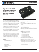
GBL2xxx Motor Controller Datasheet 3
Important Safety Disclaimer
Dangerous uncontrolled motor runaway condition can occur for a number of
reasons, including, but not limited to: command or feedback wiring failure,
configuration error, faulty firmware, errors in user script or user program, or
controller hardware failure.
The user must assume that such failures can occur and must make his/her system
safe in all conditions. Roboteq will not be liable in case of damage or injury as a
result of product misuse or failure.
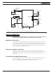
Power Wires Identifications and Connection
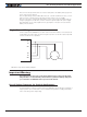
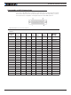
Power connections are made by means of high amperage power terminals located at the
top of the controller, as shown in Figure 1:.
I/O
Pin 25 is
Power Control
Ethernet
Motor 1 Connections
Battery - Battery +
Hall 1Status
USB
Com
Hall 2 Motor 2 Connections
U1
B-
B+
V1
W1
U2
V2
W2
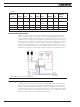
FIGURE 1. GBL26xx Rear View
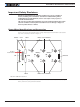
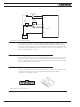
The diagram in Figure 2, below, shows how to wire the controller in a dual motor configu-
ration, and how to turn power On and Off.