
Data Sheet
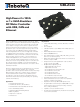

10 GBL2xxx Motor Controller Datasheet Version 1.2 July 10, 2018
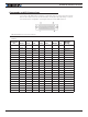
TABLE 5.
Connector
Pin Power Dout Com Pulse Ana Dinput Enc
Default
Config
24 RC7 ANA7/
ASIN2
DIN7 ENC1A Unused
12 RC8 ANA8/
ACOS2
DIN8 ENC1B Unused
25
PwrCtrl
13 GND
Note 1: Analog command is disabled in factory default configuration.
Default I/O Configuration
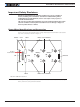
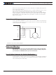
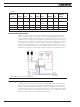
While the controller can be configured so that practically any Digital, Analog and RC pin
can be used for any pur pose, the controller’s factory default configuration provides an
assignment that is suitable for most applications. The figure below shows how to wire the
controller to two analog potentiometers, an RC radio, and the RS232 port. It also shows
how to connect two outputs to motor brake solenoids and another output to an external
status LED. You may omit any connection that is not required in your application. The con-
troller automatically arbitrates the command priorities depending on the presence of a
valid command signal in the following order: 1-RS232, 2-RC Pulse, 3-None. If needed, use
the Roborun+ PC Utility to change the pin assignments and the command prior ity order.
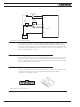
FIGURE 10. Factory Default Pin Assignment
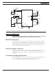
Enabling Analog Commands
For safety reasons, the Analog command mode is disabled by default. To enable the An-
alog mode, use the PC utility and set Analog in Command Priority 2 or 3 (leave Serial as
priority 1). Note that by default the additional securities are enabled and will prevent the
motor from starting unless the potentiometer is centered, or if the voltage is below 0.25V
or above 4.75V. The drawing shows suggested assignment of Pot 1 to ANA1 and Pot 2 to
ANA4. Use the PC utility to enable and assign analog inputs.