
Schematic


Motor Deactivation in Case of Output Stage Hardware Failure
Advanced Digital Motor Controller User Manual 37
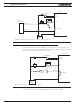
The figures below show all the possible combinations of shorted MOSFETs switches in a
brushed DC motor controller.
1
+
-
+
-
+
-
+
-
+
-
+
-
+
-
+
-
+
-
+
-
+
-
+
-
+
-
+
-
+
-
3
2
9
8
11
10
13
15 16
12
6
5
4
7
14
FIGURE 2-1. MOSFET Failures resulting in no motor activation
1
+
-
+
-
+
-
+
-
+
-
+
-
+
-
+
-
+
-
+
-
+
-
+
-
+
-
+
-
+
-
3
2
9
8
11
10
13
15 16
12
6
5
4
7
14
FIGURE 2-2. MOSFET Failures resulting in battery short circuit and no motor activation
1
+
-
+
-
+
-
+
-
+
-
+
-
+
-
+
-
+
-
+
-
+
-
+
-
+
-
+
-
+
-
3
2
9
8
11
10
13
15 16
12
6
5
4
7
14
FIGURE 2-3. MOSFET Failure resulting in motor activation
Two failure conditions (15 and 16) will result in the motor spinning out of control re-
gardless whether the controller is on or off. While these failure conditions are rare, us-
ers must take them into account and provide means to cut all power to the controller’s
power stage.