
Data Sheet

FIM2360 Motor Controller Datasheet 9
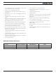
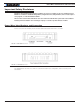
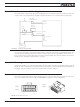
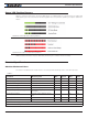
Status LED Flashing Patterns
After the controller is powered on, the Power LED will tun on, indicating that the controller is On. The Status LED
will be flashing at a 2 seconds interval. The flashing pattern and color provides operating or exception status infor-
mation.
FIGURE 9. Normal Operation Flashing Patterns
FIGURE 10. Exception or Fault Flashing Patterns
Additional status information may be obtained by monitoring the controller with the PC utility.
Electrical Specifications
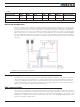
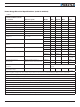
Absolute Maximum Values
The values in the table below should never be exceeded, permanent damage to the controller may result.
TABLE 3.
Parameter Measure point Min Typical Max Units
Battery Leads Voltage Ground to VBat 63 Volts
Reverse Voltage on Battery Leads Ground to VBat -1 Volts
Power Control Voltage Ground to Pwr Control wire 63 Volts
Motor Leads Voltage Ground to U, V, W wires 63 (1) Volts
Digital Output Voltage Ground to Output pins 30 Volts
Analog and Digital Inputs Voltage Ground to any signal pin on 15-pin &
Hall inputs
30 Volts
RS232 I/O pins Voltage External voltage applied to Rx/Tx
pins
30 Volts
Case Temperature Case -40 85 ºC
Humidity Case 100 (2) %
Note 1: Maximum regeneration voltage in normal operation. Never inject a DC voltage from a battery or other fixed source
Note 2: Non-condensing
Electrical Specifications