
Data Sheet

FIM2360 Motor Controller Datasheet 5
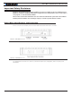
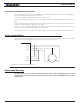
Precautions and Optional Connections
Note 1: Backup battery to ensure motor operation with weak or discharged batteries, connect a second battery to
the Power Control wire/terminal via the SW1 switch.
Note 2: Use precharge 1K, 0.5W Resistor to prevent switch arcing.
Note 3: Insert a high-current diode to ensure a return path to the battery during regeneration in case the fuse is
blown.
Note 4: Optionally ground the VMot tabs when the controller is Off if there is any concern that the motors could
be made to spin and generate voltage in excess of 60V.
Note 5: Connect the controller’s bottom plate to a wire connected to the Earth while the charger is plugged in the
AC main, or if the controller is powered by an AC power supply.
Note 6: Beware not to create a path from the ground pins on the I/O connector and the battery minus terminal.
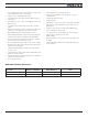
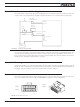
Single Channel Wiring
On the Single Channel FIM2360S, the each of the motor wire must be connected to both output tabs of the same
letter as shown in the figure below. Use the Encoder of Channel 1 for operation.
U1
V1
W1
U2
V2
W2
U
V
W
FIGURE 4. Single Channel wiring diagram
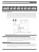
Important Warning
This wiring must be done only on the single channel version of the controller. Paralleling the wires on a dual
channel product will cause permanent damage. Verify that your controller is an FIM2360S before you wire
in this manner.
Single Channel Wiring