
Data Sheet

10 FIM2360 Motor Controller Datasheet Version 1.0 July 20, 2018
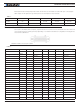
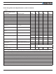
Power Stage Electrical Specifications (at 25ºC ambient)
TABLE 4.
Continuous Max Current
per channel Measure point Model Min Typical Max Units
Battery Leads Voltage Ground to VBat All 0 (1) 63 Volts
Motor Leads Voltage Ground to U, V, W wires All 0 (1) 63 (2) Volts
Power Control Voltage Ground to Power Control wire All 0 (1) 65 Volts
Minimum Operating Voltage VBat or Pwr Ctrl wires All 9 (3) Volts
Over Voltage protection range Ground to VBat All 5 60 (4) 63 Volts
Under Voltage protection range Ground to VBat All 0 5 (4) 63 Volts
Idle Current Consumption VBat or Pwr Ctrl wires All 50 100 (5) 150 mA
ON Resistance (Excluding wire
resistance)
VBat to U, V or W. Ground to
U, V or W
FIM23xx 2.5 mOhm
FIM23xxS 1.25 mOhm
Max Current for 30s Motor current FIM23xx 60 Amps
FIM23xxS 120 Amps
Continuous Max Current per
channel
Motor current FIM23xx 40 (6) Amps
FIM23xxS 80 (6) Amps
Current Limit range Motor current FIM23xx 10 50 (7) 60 Amps
FIM23xxS 20 100 (7) 120 Amps
Stall Detection Amps range Motor current FIM23xx 10 60 (7)
60
Amps
FIM23xxS 20 120 (7)
120
Amps
Stall Detection timeout range Motor current All 1 500 (8)
65000
milli-
seconds
Short Circuit Detection
threshold (9)
Between Motor wires or
Between Motor wires and round
FIM23xx
150 (10)
Amps
FIM23xxS
300 (10)
Amps
Short Circuit Detection
threshold
Between Motor wires and VBat All No Protection. Permanent damage will
result
Motor Acceleration/
Deceleration range
Motor Output
All 100 500 (11) 65000 milli-
seconds
Note 1: Negative voltage will cause a large surge current. Protection fuse needed if battery polarity inversion is possible
Note 2: Maximum regeneration voltage in normal operation. Never inject a DC voltage from a battery or other fixed source
Note 3: Minimum voltage must be present on VBat or Power Control wire
Note 4: Factory default value. Adjustable in 0.1V increments
Note 5: Current consumption is lower when higher voltage is applied to the controller’s VBat or PwrCtrl wires
Note 6: Estimate. Limited by case temperature. Current may be higher with better cooling
Note 7: Factory default value. Adjustable in 0.1A increments
Note 8: Factory default value. Time in ms that Stall current must be exceeded for detection
Note 9: Controller will stop until restarted in case of short circuit detection
Note 10: Approximate value
Note 11: Factory default value. Time in ms for power to go from 0 to 100%