
Data Sheet

Trapezoidal Switching
Advanced Digital Motor Controller User Manual 95
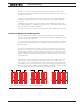
The reply is one or two numbers depending whether the controller is a single or dual
channel. The values is between 0 and 7 with each bit representing the state of each of the
HA, HB and HC sensors.
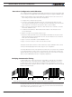
Turn the motor slowly by hand while sending frequent ?HS queries. Verify that all valid
combinations appear at one time or the other and that none of the invalid combination
ever show.
For 60 degrees spaced Hall sensors, 0-1- 3-4- 6-7 are valid combinations, while 2 and 5
are invalid combinations. For 120 degrees spaced sensors, 1-2- 3-4- 5-6 are valid combina-
tions, while 0 and 7 are invalid combinations.
Note that HS query does not work on the first generation HBL and VBL family of products.
Hall Sensor Alignment and Wiring Order
It is very important that the hall sensors be precisely aligned vs the electromagnets in-
side the motor so that commutation be done exactly at the right time. Bad alignment will
cause the motor to run inefficiently.
The order of the Hall sensors and these of the motor connections must match in order for
the motor to spin. Unfortunately, there is no standard naming and ordering convention for
brushless motors.
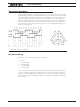
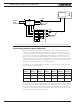
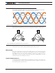
The Hall Sensor and Motor Phases naming convention used in Roboteq controllers is A,
B and C for the sensors and U, V and W for the motor phases. When rotating the motor
shaft clockwise by hand, the controllers expects the sensor A to be a mirror of the voltage
generated between wires U and W, sensor B between V and U, sensor C between W
and V. See figure 8-4. The sinewave voltage will be inverted when turning the motor in the
opposite direction.
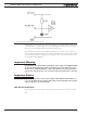
Alternatively, in order to synchronize the wiring order of the motor winding and the hall
sensor wires, the HSM configuration command can be used (see “HSM” in the com-
mand reference section). For each hall sensor cable order and motor wire order, there are
6 combinations, one of which will make the motor spin smoothly and efficiently in both
direction. Try each of the 6 available values of HSM (0-5) and retain the one that will make
the motor spin in both directions while drawing the same low current.
Vv-u Vw-vVu-w
Va Vb Vc
Figure 8-4. Relation between hall sensor and U V W windings