
Data Sheet

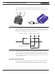

Brushless Motor Connections and Operation
78 Advanced Digital Motor Controller User Manual V1.8, August 28 2017
Important Warning
Some receivers include their own supervision of the radio signals and will move
their servo outputs to a safe position in case of signal loss. Using these types of re-
ceiver, the controller will always be receiving pulses even with the transmitter off.
Using Sensors with PWM Outputs for Commands
The controller’s Pulse inputs can be used with various types of angular sensors that use
contactless Hall technology and that output a PWM signal. These type of sensors are
increasingly used inside joysticks and will perform much more reliably, and typically with
higher precision than traditional potentiometers.
The pulse shape output from these devices varies widely from one sensor model to an-
other and is typically different than this of RC radios:
- They have a higher repeat rate, up to a couple of kHz.
- The min and max pulse width can reach the full period of the pulse
Care must therefore be exercised when selecting a sensor. The controller will accommo-
date any pulsing sensor as long as the pulsing frequency does not exceed 250Hz. The
sensor should not have pulses that become too narrow - or disappear altogether - at the
extremes of their travel. Select sensors with a minimum pulse width of 10us or higher.
Alternatively, limit mechanically the travel of the sensor to keep the minimum pulse width
within the acceptable range.
A minimum of pulsing must always be present. Without it, the signal will be considered as
invalid and lost.
Pulses from PWM sensors can be applied to any Pulse input on the controller’s connector.
Configure the input capture as Pulse or Duty Cycle.
A Pulse mode capture measures the On time of the pulse, regardless of the pulse period.
A Duty Cycle mode capture measures the On time of the pulse relative to the entire pulse
period. This mode is typically more precise as it compensates for the frequency drifts o
the PWM oscillator.
PWM signals are then processed exactly the same way as RC pulses. Refer to the RC
pulse paragraphs above for reference.
Operating the Controller In Analog Mode
Analog Command is the simplest and most common method when the controller is used
in a non-remote, human-operated system, such as Electric Vehicles.
Input Analog Channel Selection
The controller features 4 to 11 inputs, depending on the model type, that can be used for
analog capture. Using different configuration parameters, any Analog input can be used as
command for any motor channel. The controller’s factory default defines two channels as