
Data Sheet


Magnetic Guide Sensor Connection and Operation
68 Advanced Digital Motor Controller User Manual V1.8, August 28, 2017
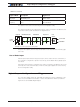
MagSensor MultiPWM interface
The recommended interfacing method to Roboteq motor controller is the MagSensor
MultiPWM mode. As the name implies, this proprietary method uses a succession
of variable duty-cycle pulses to carry the Tracks, Tape Detect, Markers and Gyroscope
information.
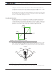
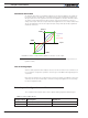
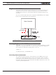
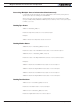
Any of the controller’s pulse input can be configured as a MultiPWM input. The diagram
below shows how simple this one-wire interfacing is.
Motor Controller
Senso
r
MultiPWM
Pulse Input
GND
5V Out or
7-30V Supply
Figure 5-1: One-wire interfacing using MultiPWM
Enabling MagSensor MultiPWM Communication
MGS1600 Sensor is set to MultiPWM mode in its factory default configuration. To enable
capture, the selected pulse input on the controller must be configured to “MagSensor”
when using the PC utility. When changing via the console use
^PMOD cc 4
To enable pulse input cc in MultiPWM mode.
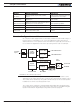
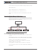
Accessing Sensor Information
Once enabled, the pulses are sent continuously by the sensor 100 times per second.
The pulses are captured and parsed by the motor controller as they arrive. A real time
mirror image of sensor data is then present inside the controller. From there the sensor
information can be read using serial, USB, CAN or MicroBasic scripts like any other of the
controller’s operational parameters.