
Data Sheet


Digital Outputs Configurations and Triggers
Advanced Digital Motor Controller User Manual 63
TABLE 4-3. (continued)
Catpure Mode Description Typical use
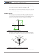
Duty Cycle
Measures the On time relative to the
full On/Off period
Hall position sensors and joysticks with
pulse output
Frequency
Measures the repeating frequency of
pulse
Encoder wheel
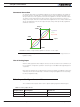
The capture mode can be selected using the PC Configuration Utility.
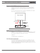
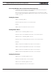
The captured signals are then adjusted and can be used as command or feedback accord-
ing to the processing chain described in the diagram below.
Min/Max/CenterCapture
P
ulse
Input
Command
Feedback
Deadband Exponent
Use
Select
FIGURE 4-8. Pulse Input processing chain
Except for the capture, all other steps are identical to these described for the Analog cap-
ture mode.
Use of Pulse Input
After the pulse input has been fully processed, it can be used as a motor command or, if
the controller is configured to operate in closed loop, as a feedback value (typically speed
or position).
Each input can therefore be configured to be used as command or feedback for any motor
channel(s). The mode and channel(s) to which the analog input applies are selected using
the PC Configuration Utility.
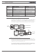
Digital Outputs Configurations and Triggers
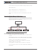
The controller’s digital outputs can individually be mapped to turn On or Off based on the
status of user-selectable internal status or events. The table below lists the possible as-
signment for each available Digital Output.