
Data Sheet

Connecting the Encoder
Advanced Digital Motor Controller User Manual 55
Specifically, the controller’s encoder interface can process 1 million counts per second,
unless otherwise specified in the product datasheet.
Commercial encoders are rated by their numbers of “Pulses per Revolution” (also some-
times referred as “Number of Lines” or “Cycles per Revolution”). Carefully read the manu-
facturer’s datasheet to understand whether this number represents the number of pulses
that are output by each channel during the course of a 360 degrees revolution rather than
the total number of transitions on both channels during a 360 degrees revolution. The sec-
ond number is 4 times larger than the first one.
The formula below gives the pulse frequency at a given RPM and encoder resolution in
Pulses per Revolution.
Pulse Frequency in counts per second = RPM / 60 * PPR * 4
Example: a motor spinning at 10,000 RPM max, with an encoder with 200 Pulses per Rev-
olution would generate:
10,000 / 60 * 200 * 4 = 133.3 kHz which is well within the 1MHz maximum supported by
the encoder input.
An encoder with a 200 Pulses per Revolutions is a good choice for most applications.
A higher resolution will cause the counter to count faster than necessary and possibly
reach the controller’s maximum frequency limit.
An encoder with a much lower resolution will cause speed to be measured with less precision.
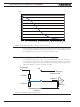
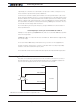
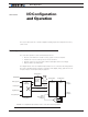
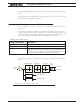
Connecting the Encoder
Encoders connect directly to pins present on the controller’s connector. The connector
provides 5V power to the encoders and has inputs for the two quadrature signals from
each encoder. The figure below shows the connection to the encoder.
Encoder
Controller
GND
5V Out
ENC1A (ENC2A)
Ch A
Ch B
ENC1B (ENC2B)
5V
GND
FIGURE 3-18. Controller connection to typical Encoder