
Data Sheet


Connecting Sensors and Actuators to Input/Outputs
48 Advanced Digital Motor Controller User Manual V1.8, August 28, 2017
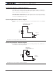
33kOhm
20kOhm
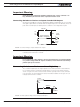
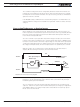
Internal Resistors
and Converter
+5V
Ground
A/D
10kOhm 5kOhm
+/-1
0V
10kOhm
Figure 3-8. External resistors circuit for -10V to 10V capture range
Important Notice
On newer motor controllers models, activating the pulse mode on an input will also
enable a pull up resistor on that input. If the input is also used for analog capture,
the analog reading will be wrong. Make sure the pulse mode is disabled on that
input.
Reducing noise on Analog Inputs
The Analog inputs are very fast and have a high input resistance. They will therefore eas-
ily be disturbed by ambient electrical noise and this will cause the analog reading to be
fluctuating. Use shielded cables between the input and the analog sensor. Add a 1uF ca-
pacitor between the input pin and the GND pin. With good shielding and filtering, a signal
stable to withing +/-5V or better can generally be achieved.
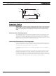
Connecting Potentiometers to Analog Inputs
Potentiometers mounted on a foot pedal or inside a joystick are an effective method for
giving command to the controller. In closed loop mode, a potentiometer is typically used
to provide position feedback information to the controller.
Connecting the potentiometer to the controller is as simple as shown in the diagram on
Figure 3-9.
The potentiometer value is limited at the low end by the current that will flow through it
and which should ideally not exceed 5 or 10mA. If the potentiometer value is too high,
the analog voltage at the pot’s middle point will be distorted by the input’s resistance to
ground of 53K. A high value potentiometer also makes the input sensitive to noise, partic-
ularly if wiring is long. Potentiometers of 1K or 5K are recommended values.