
Data Sheet

Run Tab
Advanced Digital Motor Controller User Manual 377
The DefConfig Fault LED will also turn on the first time the controller is restarted after a
new firmware release has be installed and default configuration first reloaded.
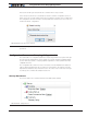
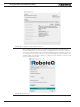
Applying Motor Commands
The command sliders will cause the command value to be applied to the controller. Click-
ing on the “+”, “++”, “-”, “--” buttons lets you fine-tune the command that is applied to the
controller. The numerical value can be entered manually by entering a number in the text
box.
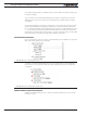
The “Mute” checkbox can be selected to stop all commands from being sent to the
controller. When this is done, only parameter reads are performed. When commands are
muted and if the watchdog timer is enabled, the controller will detect a loss of commands
arriving from the serial port and depending on the priorities it will switch back to the RC or
Analog mode.
If a USB Joystick is connected to the PC and the “Enable” box is checked, the slider will
update in real-time with the captured joystick position value. This makes it possible to
operate the motor with the joystick. The “Configure Joystick” button lets you perform ad-
ditional adjustments such as inverting and swapping joystick input.
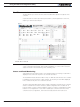
FIGURE 20-24
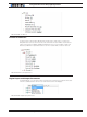
Digital, Analog and Pulse Input Monitoring
The status of Digital inputs and the value Analog and Pulse can be monitored in real-time.
Analog and Pulse inputs will update only if the selected channel is enabled. The labels for
the digital inputs, digital outputs, analog inputs and pulse inputs can be made to take the
value that has been entered in the configuration tree as described in Input/Output Label-
ing. Using a nickname for that signal makes it easier to monitor that information.
Digital Output Activation and Monitoring
The Digital output LEDs reflect the actual state of each of the controller’s Output. If an
output is not changed by the controller using one of the available automatic Output Trig-
gers (see “DOA” on page 200), clicking on the LED will cause the selected output to tog-
gle On and Off.
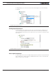
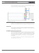
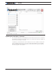
Using the Chart Recorder
A powerful chart recorder is provided for real-time capture and plotting of operating param-
eters. This chart can display up to eight operating parameters at the same time. Each of
the chart’s channels has a pull-down menu that shows all of the operating parameters that
can be viewed and plotted. The colors can be changed by clicking on the color icon and
selecting another color.
When selecting a parameter to display, this parameter will appear in the chart and change
in real-time. The three boxes show a numerical representation of the actual value and the
Min and Max value reached by this input. Clicking on the “Clear” button for that channel