
Data Sheet
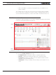

Program Launch and Controller Discovery
Advanced Digital Motor Controller User Manual 369
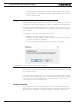
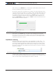
When clicking on the “Calibrate” link, a window pops up that displays a bar showing the
live value of that analog or pulse input in real time.
The window contains three cursors that move in relation to the input, capturing the mini-
mum and maximum detected values. It is possible to further manually adjust further these
settings by moving the sliders. The Center value will be either the value of the inputs (or
the joystick position) at the time when clicking on the “Done” button. The Center value
can also be automatically computed to be the middle between Min and Max when en-
abling the “Auto Center” checkbox. Clicking on “Reset” resets the Min, Max and Center
sliders and lets you restart the operation.
FIGURE 20-7. Auto calibration window
After clicking on the “Done” button, the capture values will appear in the Min, Max
and Center nodes in the tree with the orange * next to them, indicating that they have
changed but not yet be saved in the controller. At this point, they can be adjusted further
manually and saved in the controller.
Input/Output Labeling
Each analog, digital or pulse input/output, is given default label (e.g. DIN1, AIN2, ...). Al-
ternatively, it is possible to assign or a user defined label name (e.g. Limit1, eStop, ...) to
each of these signals. This label will then appear in the Run Tab next to the LED or Value
box. The label will also appear in the Pin View window (See Figure 67, “Pinout view pop-
up window,” on page 227). Custom labels make it much easier to monitor the controller’s
activity in the Run tab.
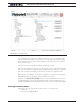
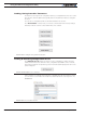
FIGURE 20-8. Labeling an Input/Output
To label an Input or Output, simply select it in the tree. A text field will appear in which
you can enter the label name. Beware that while it is possible to enter a long label, names
with more than 8 letters will typically appear truncated in the Run tab.