
Data Sheet


AC-induction-Motor-Operation
120 Advanced Digital Motor Controller User Manual V1.8, August 28, 2017
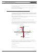
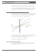
• Put some high load on the rotor and command a step Torque Amps from the slider bar
(say 10A). Record the “FOC Torque Amps” reading on the chart. If the step response
reaches the desired (10A) steady state fast enough then the PID is can be considered
tuned. If it is slow then increase integral gain. If the Torque and Flux Amps show noise
at high speed or motor produces noisy sound, then lower your proportional gain Kp.
• Once FOC/current PID is tuned, FOC torque mode is ready to operate and FOC speed
mode can then be tuned. Note: It is important to know the value of Flux Amps the mo-
tor is designed to operate under. Flux Amps stay the same during entire FOC operation
unless field weakening is used.
Now motor Torque can be set to any desired value from 0 to plus or minus the value stored
in the Amps Limit configuration parameter, by sending a command of -1000 to +1000 using
the slider, analog input, pulse input, scripting, CAN or any other command mode.
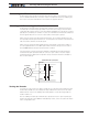
Note that in Torque Mode, the Max Speed RPM configuration parameter is used to limit
the motor speed if the motor is not loaded and the desired torque is below the torque
that can actually be reached by the motor under the current load conditions. For example,
a torque command of 50A on an unloaded motor (that will never draw 50A) will cause the
voltage to increase to maximum value, and therefore the motor to maximum speed, un-
less the speed is limited by the Max RPM parameter.
Configuring FOC Speed Mode
To configure FOC Speed mode, configure first the FOC Torque mode as described in the
section above.
• Set the controller to FOC Speed Mode
• Tune speed loop PID in a similar manner as was done for FOC PID. Use the PID gains
found in the Motor Output, Closed Loop Speed Parameters menus (do not use the
FOC PID gains). It can be started with Kp term and introduce small Kd term. Once
transient response on the graph seems reasonable then Ki can be used to get rid of
steady state error.
Now motor Speed can be set to any desired value from 0 to plus or minus the value stored
in the Max RPM configuration parameter, by sending a command of -1000 to +1000 using
the slider, analog input, pulse input, scripting, CAN or any other command mode.
E.g. use the Roborun slider, or the console command
!G 1 800
to set motor RPM to 800 on channel 1 when MaxSpeed is set to 1000 RPM. Correspond-
ing if MaxSpeed is set to 2000 RPM, any value on the slider will give 2 times RPM.
Speed can be also set as an absolute RPM value using the S command from Serial, USB,
CAN or Microbasic