
Data Sheet


AC-induction-Motor-Operation
118 Advanced Digital Motor Controller User Manual V1.8, August 28, 2017
• Set the PID gains found in the Motor Output, Closed Loop Speed Parameters menus
(do not use the FOC PID gains). Try first with gains of P=4, I=0.5, D=0. These values
will produce adequate results in most cases. Additional turning may be needed.
• Set the Max RPM configuration to the speed that must be reached at full throttle (ie
when command = 1000). Make sure to enter a value that is within the physical reach of
the motor under the expected maximum load condition.
• Enter the lowest acceleration rate that is acceptable for the application. Rapid chang-
es will create current surges and should therefore not be allowed to be higher than
necessary.
• Save the settings to the controller.
The motor speed can now be set to be any value between 0 and plus/minus the max-
imum RPM configured above when sending a command ranging from -1000 to +1000
using the serial, analog or pulse inputs.
The motor speed can also be set to an absolute RPM value by sending the S (Speed)
command via serial, USB, CAN or Scripting.
When exercising the motor with the PC utility, monitor the Slip, the Rotor RPM, Stator
RPM and the Motor Amps. The Rotor RPM can be viewed in the Encoder RPM chart. The
Stator RPM can be viewed in the Hall RPM chart.
The slip will stabilize at of the Optimal Slip setting.
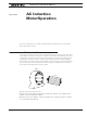
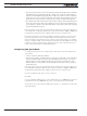
Field Oriented Control (FOC) mode Operation
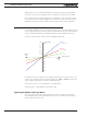
Field Oriented Control (or Vector Drive) is a technique by which the magnetic field gen-
erated in the stator is adjusted in relation to the field induced in the rotor in a manner to
generate optimal torque at all times and all load conditions.
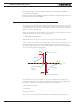
I
Iq
Id
S
S
N
N
Rotor
Stator
Optimal rotation occurs when the magnetic field induced in the rotor is perpendicular
with this of stator. Practically the fields the two fields are never exactly perpendicular. As
shown on the diagram above, the angled field I is made of an outward pulling flux field (Id)
and perpendicular pulling torque field. The torque field is the one that causes the rotation
and that the controller will maximize. Flux field is not causing any rotation and therefore
must be minimized. Some flux is necessary at all times, however, in order to create the
induction in the rotor.
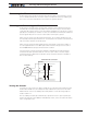
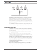
The challenge in induction motors is that the rotor flux’s absolute position cannot be mea-
sured physically. It is determined mathematically using known speed, voltage and current,
and a model representation of the motor’s main parameters shown in the figure below.