
Data Sheet

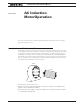

AC-induction-Motor-Operation
116 Advanced Digital Motor Controller User Manual V1.8, August 28, 2017
Apply a positive motor command. Verify that the motor shaft is moving in the desired direc-
tion. If the motor moves in the opposite direction, swap any two of the three motor cables.
If the motor moved in the desired direction, then verify that the encoder counter increments
when a positive motor command is applied. If the counter decrements, then either swap the
A and B encoder wires, or enter a negative number of PPRs in the encoder configuration.
Open Loop Variable Frequency Drive Operation
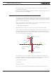
In its simplest operating mode, the controller will output to the motor a three-phase sinusoid
whose voltage and frequency change together at a fixed ratio. This mode is called Scalar be-
cause of the fixed ratio between the Voltage and Frequency that is applied to the motor.
The ratio is set by the VPH - Volts Per Hertz configuration parameter.
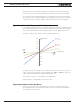
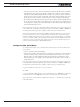
-1000
-800
-600
-400
-200
200
400
600
800
1000
-1000
0
1000
Stator Frequency
(Hz)
Motor Command
48V Battery
VpH = 0.05 V/Hz
48V Battery
VpH = 0.1V/Hz
24V Battery
VpH = 0.1V/Hz
+ Battery
Volts
- Battery
Volts
The figure above shows example of the resulting stator frequency for a given motor com-
mand. In open loop mode, Motor commands range from -1000 to +1000 and result in the
output voltage to range between -VBat to +VBat respectively
As long as the motor is not overloaded, the rotor RPM will be
((Stator Frequency - Slip) / Number of Pole Pairs) * 60
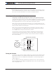
Figuring the Motor’s Volts per Hertz
Each motor has a value for the optimal Volts per Hertz ratio. It can be determined by
the operating frequency and rated voltage written of the motor’s label. The figure below
shows values from a real motor.