
Data Sheet


6 FDC3260 Motor Controller Datasheet Version 1.0. December 19, 2014
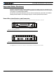
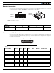
Encoder Connection
Connection to the Encoders is done using a special connector on the front side of the controller. The connector is
a 10-pin Molex Microfit 3.0, ref. 43025-1000. Pin assignment is in the table below.
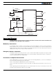
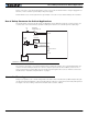
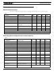
Commands and I/O Connections
Connection to RC Radio, Microcomputer, Joystick and other low current sensors and actuators is done via the 25
connector. The functions of many pins vary depending on controller model and user configuration. Pin assignment
is found in the table below.
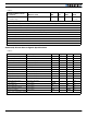
TABLE 1.
Pin Number 1 2 3 4 5
Row Ch1 5V Enc3 A Enc1 B Enc1 A Ground
Row Ch2 5V Enc3 B Enc2 B Enc2 A Ground
TABLE 2.
Connector Pin Power Dout Com Pulse Ana Dinput Default Config
1 GND
14 5VOut
2 RS TxD RS232Tx
15 RC1 ANA1 DIN1 RCRadio1
3 RS RxD RS232Rx
16 RC2 ANA2 DIN2 RCRadio2
4 RC3 ANA3 DIN3 AnaCmd1 (1)
17 RC4 ANA4 DIN4 AnaCmd2 (1)
5 GND
18 DOUT1 Motor Brake 1
6 DOUT2 Motor Brake 2
19 DOUT3 Contactor
1
Row Ch2
Row Ch2
Row Ch1
Row Ch1
1
5
5
FIGURE 5. Encoder connector
1 13
14 25
FIGURE 6. Main Connector pin locations