
Data Sheet


8 FBL2360 Motor Controller Datasheet Version 1.0. June 09, 2015
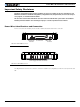
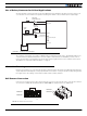
Connection to Analog Sin/Cos Absolute Encoder
The FBL2360 has 4 high-speed analog inputs that can be used to capture absolute angle position from resolvers
or magnetic sensors with sin/cos voltage outputs. The signal must be 0-5V max with the 0 at 2.500V. The table
below shows the signals assignment on the 25-pin connector.
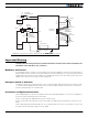
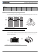
Commands and I/O Connections
Connection to RC Radio, Microcomputer, Joystick and other low current sensors and actuators is done via the 25
connector. The functions of many pins vary depending on controller model and user configuration. Pin assignment
is found in the table below.
TABLE 1.
Pin Number 1 2 3 4 5
Row 1 5V NC NC Sel GND
Row 2 5V Clock Data 1 Data 2 GND
TABLE 2.
Signal Pin Number Pin Name
Sin1 9 ASIN1
Cos1 10 ACOS1
Sin2 24 ANA7/ASIN2
Cos2 12 ANA8/ACOS2
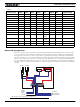
TABLE 3.
Connector Pin Power Dout Com Pulse Ana Dinput Enc Default Config
1 GND
14 5VOut
2 RS TxD RS232Tx
15 RC1 ANA1 DIN1 RCRadio1
3 RS RxD RS232Rx
16 RC2 ANA2 DIN2 RCRadio2
4 RC3 ANA3 DIN3 AnaCmd1 (1)
17 RC4 ANA4 DIN4 AnaCmd2 (1)
5 GND
18 DOUT1 Motor Brake 1
6 DOUT2 Motor Brake 2
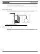
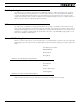
113
14 25
FIGURE 9. Main Connector pin locations