
Data Sheet


FBL2360 Motor Controller Datasheet 7
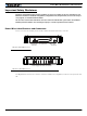
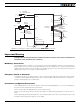
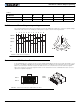
Hall Sensor vs Motor Output sequencing
Hall Sensor vs Motor Output sequencing
The controller requires the Hall sensors inside the motor to be 120 degrees apart. The controller’s 3-phase bridge
will activate each of the motor winding according to the sequence shown in the figure below.
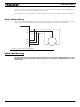
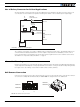
Connection to SPI Absolute Encoder
In Sinusoidal Mode, the controller can use motors equipped with absolute angle sensors with SPI interface, such
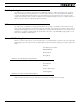
as found on the BL167 or BL90 motors from Micromotor. When enabled, the SPI signals are found on the 10-pin
Molex connector that is otherwise used for the Hall Sensors. The controller issues a clock and select signal.
When two motors are used, these signals must be connected to both sensors. Serial data from each sensor is
captured on separate input pins.
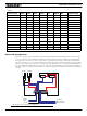
TABLE 1.
Pin Number 1 2 3 4 5
Row Ch1 5V Hall1 C Hall1 B Hall1 A Ground
Row Ch2 5V Hall2 C Hall2 B Hall2 A Ground
U
VW
1234561
4
2
5
3
6
4
1
5
2
6
3
Hall A
Hall B
Hall C
U
V
W
+
--
-- --
-- --
--
++ ++
++ ++
++ +
FIGURE 7. Hall Sensors sequence
1
Row 2
Row 2
Row 1
Row 1
1
5
5
FIGURE 8. Hall Sensor connector used for SPI encoders