
Manual

Copyright © Roboteq Inc. 2018. All Rights Reserved. 14
3.2 0X6041 - STATUS WORD
Table 12 gives a short description of the object, Table 13 the mapping of the respective
variable and Table 14 the usage of the bits that are independent to operation mode.
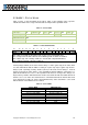
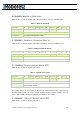
TABLE 12 - STATUS WORD
Sub-Index
00
Optional
N
Type
U16
Access
RO
PDO
T
Value Range
Discrete
Default
-
RoboCommand
SW
Description
The status of the PDS FSA.
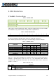
TABLE 13 - STATUS WORD MAPPING
15
14
13
12
11
10
9
8
7
6
5
4
3
2
1
0
NU
OMS
ILA
TR
RM
MS
W
SOD
QS
VE
F
OE
SO
RTSO
MSB
LSB
NU Not Used, OMS Operation mode specific, ILA Internal limit active
TR Target reached, RM Remote, W Warning, SOD Switch on disabled,
QS Quick stop, VE Voltage enabled, F Fault, OE Operation Enabled,
SO Switch on RTSO Ready to switch on.
If bit 4 (voltage enabled) of the status word is always 1. If bit 5 (quick stop) of the status word
is 0, this shall indicate that the PDS is reacting on a quick stop request (quick stop mode is
always 2). Bit 7 (warning) is always 0. Bit 9 (remote) of the status word is always 1. If bit 10
(target reached) of the status word is 1, this shall indicate that the PDS has reached the set-
point. Bit 10 shall also be set to 1, if the operation mode has been changed. The change of a
target value by software shall alter this bit. If halt occurred and the PDS has halted then bit 10
shall be set to 1, too. If the same internal value is commanded then bit 10 shall not alter, if bit
10 is supported(see Table 15). If bit 11 (internal limit active) of the statusword is 1, this shall
indicate that an current limit has been reached.
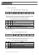
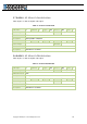
TABLE 14 - STATE CODING
Status Word
PDS FSA state
xxxx xxxx x0xx 0000
b
Not ready to switch on
xxxx xxxx x1xx 0000
b
Switch on disabled
xxxx xxxx x01x 0001
b
Ready to switch on
xxxx xxxx x01x 0011
b
Switched on
xxxx xxxx x01x 0111
b
Operation enabled
xxxx xxxx x00x 0111
b
Quick stop active
xxxx xxxx x0xx 1111
b
Fault reaction active
xxxx xxxx x0xx 1000
b
Fault