
Manual

Copyright © Roboteq Inc. 2018. All Rights Reserved. 13
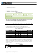
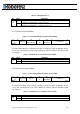
3.1.1 PROFILE POSITION MODE
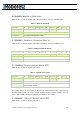
TABLE 8 - CONTROL WORD MAPPING IN PROFILE POSITION MODE
15
10
9
8
7
6
5
4
3
0
see Table 4
Change on
set-point
Halt
see
Table 4
Abs/rel
Change Set
Immediately
New Set
Point
see Table 4
MSB
LSB
In Profile Position Mode the operation specific bits are mapped in Table 8. With bits 4, 5 and
9, user can define when the command for next Position (0x607A - POS) will be processed. Bit
6 defines whether the command is absolute or relative to the current position.
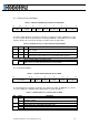
TABLE 9 - DEFINITION OF BITS 4,5,6 AND 9 IN PROFILE POSITION MODE
Bit 9
Bit 5
Bit 4
Definition
0
0
0->1
Positioning shall be completed (target reached) before the next one
gets started.
X
1
0->1
Next positioning shall be started immediately
1
0
0->1
Positioning with the current profile velocity up to the current set-point
shall be proceeded and then next positioning shall be applied
Bit
Value
Definition
6
0
Target position shall be an absolute value
1
Target position shall be a relative value. Positioning moves shall be performed
relative to the preceding (internal absolute) target position
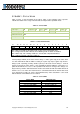
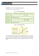
3.1.2 VELOCITY MODE
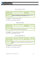
TABLE 10 - CONTROL WORD MAPPING IN VELOCITY MODE
15
9
8
7
6
5
4
3
0
see Table 4
Halt
see
Table 4
Reference
Ramp
Unlock
Ramp
Enable
Ramp
see Table 4
MSB
LSB
In Velocity Mode the operation specific bits are mapped on Table 10. With bits 4, 5 and 6,
user can configure the available ramp related options as shown in Table 11.
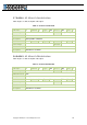
TABLE 11 - DEFINITION OF BITS 4,5 AND 6 IN VELOCITY MODE
Bit
Value
Definition
4
0
Motor shall be halted. Slow down on quick stop ramp (EDEC) and stay in
operation enabled
1
Velocity demand value shall accord with ramp output value
5
0
Ramp output value shall be locked to current output value
1
Ramp output value shall follow ramp input value
6
0
Ramp input value shall be set to zero
1
Ramp input value shall accord with ramp reference