
Manual

Copyright © Roboteq Inc. 2018. All Rights Reserved. 12
3. SDO DESCRIPTION
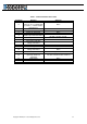
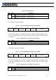
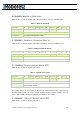
3.1 0X6040 - CONTROL WORD
TABLE 4 - CONTROL WORD
Sub-Index
00
Optional
N
Type
U16
Access
RW
PDO
R
Value Range
Discrete
Default
Operation specific
RoboCommand
CW
Description
The received command in order to control the PDS FSA.
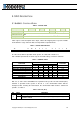
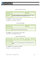
Table 4 gives a short description of the object, Table 5 the mapping of the respective variable
and Table 6 the usage of the bits that are independent to operation mode.
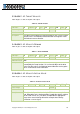
TABLE 5 - CONTROL WORD MAPPING
15
11
10
9
8
7
6
4
3
2
1
0
R
R
OMS
H
FR
OMS
EO
QS
EV
SO
MSB
LSB
R Reserved, OMS Operation mode specific, H Halt, FR Fault reset,
EO Enable operation QS Quick stop, EV Enable voltage, and SO Switch on
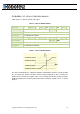
TABLE 6 - COMMAND CODING
Command
Bits of the Control Word
Transition
Bit 7
Bit 3
Bit 2
Bit 1
Bit 0
Shutdown
0
X
1
1
1
2,6,8
Switch On
0
0
1
1
1
3
Switch On + Enable Operation
0
1
1
1
1
3+4
Disable Voltage
0
X
X
0
X
7,9,10,12
Quick Stop
0
X
0
1
X
7,10,11
Disable Operation
0
0
1
1
1
5
Enable Operation
0
1
1
1
1
4,16
Fault Reset
0->1
X
X
X
X
15
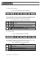
Bits 9, 6, 5, and 4 of the ControlWord are operation mode specific. The halt function (bit 8)
behavior is operation mode specific. If the bit is 1, the commanded motion shall be
interrupted, After releasing the halt function, the commanded motion shall be continued if
possible, see Table 7.
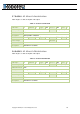
TABLE 7 - HALT BIT (BIT 8)
Bit
Value
Definition
8
0
Positioning shall be executed or continued
1
Axis shall be stopped. Slow down on quick stop ramp (EDEC) and stay in
operation enabled