
Data Sheet


FBL2360 Brushless DC Motor Controller Datasheet 9
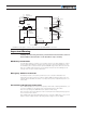
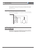
Primary
Secondary 1
Channel
1
Channel
2
ASIN1
ACOS1
Secondary 2
Primary
Secondary 1
ASIN2
ACOS2
EXC
GND
Secondary 2
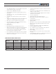
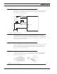
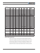
The table below shows the signals assignment on the 25-pin connector.
TABLE 5.
Signal Pin Number Pin Name
Sin1 9 ASIN1
Cos1 10 ACOS1
Sin2 24 ANA7/ASIN2
Cos2 12 ANA8/ACOS2
Exc 17 ANA4/EXC
GND 1-3 or 13 GND
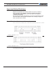
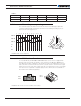
Commands and I/O Connections
Connection to RC Radio, Microcomputer, Joystick and other low current sensors and actu-
ators is done via the 25 connector. The functions of many pins vary depending on control-
ler model and user configuration. Pin assignment is found in the table below.
FIGURE 9. Main Connector pin locations
Commands and I/O Connections