
Data Sheet


8 FBL2360 Brushless DC Motor Controller Datasheet Version 1.1, May 24, 2018
TABLE 2.
Pin Number 1 2 3 4 5
Row 1 5V NC NC Sel GND
Row 2 5V Clock Data 2 Data 1 GND
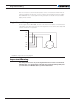
Connection to SSI Absolute Encoder
In Sinusoidal Mode, the controller can use motors equipped with absolute angle sensors
with SSI interface. When enabled, the SSI signals are found on the 10-pin Molex connec-
tor that is otherwise used for the Hall Sensors. The controller issues a differencial clock
signal and expects a 12-bit differencial data signal from the encoder. When two motors are
used, these signals must be connected to both sensors. Serial data from each sensor is
captured on separate input pins. The SSI Encoder is only featured on ‘A’ and ‘E’ versions of
Roboteq products.
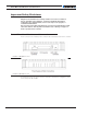
TABLE 3.
Pin Number 1 2 3 4 5
Row 1 5V CLK – Data 2 – Data 1 – GND
Row 2 5V Clock + Data 2 + Data 1 + GND
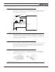
Connection to Analog Sin/Cos Absolute Encoder
The FBL2360 has 4 high-speed analog inputs that can be used to capture absolute angle
position from resolvers or magnetic sensors with sin/cos voltage outputs. The signal must
be 0-5V max with the 0 at 2.500V. The table below shows the signals assignment on the
25-pin connector.
TABLE 4.
Signal Pin Number Pin Name
Sin1 9 ASIN1
Cos1 10 ACOS1
Sin2 24 ANA7/ASIN2
Cos2 12 ANA8/ACOS2
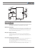
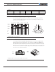
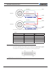
Connecting Resolver
Resolver wiring is similar to a Sin/Cos sensor with the addition of an excitation signal.
Diagram below shows the necessary connections.