
Data Sheet


FBL2360 Brushless DC Motor Controller Datasheet 5
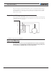
Single Channel Wiring
Note 5: Connect the controller’s bottom plate to a wire connected to the Earth while the
charger is plugged in the AC main, or if the controller is powered by an AC power supply.
Note 6: Beware not to create a path from the ground pins on the I/O connector and the
battery minus terminal.
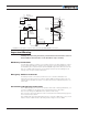
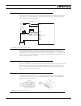
Single Channel Wiring
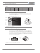
On the Single Channel FBL2360S, the each of the motor wire must be connected to both
output tabs of the same letter as shown in the figure below. Use the Encoders and/or Hall
sensors of Channel 1 for operation.
FIGURE 4. Single Channel wiring diagram
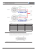
Important Warning
This wiring must be done only on the single channel version of the controller. Paral-
leling the wires on a dual channel product will cause permanent damage. Verify that
your controller is an FBL2360S before you wire in this manner.
U1
V1
W1
U2
V2
W2
U
V
W