
Data Sheet


FBL2360 Brushless DC Motor Controller Datasheet 15
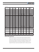
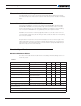
TABLE 8.
Continuous Max
Current per channel Measure point Model Min Ty p Max Units
Note 6: Estimate. Limited by case temperature. Current may be higher with better cooling
Note 7: Factory default value. Adjustable in 0.1A increments
Note 8: Factory default value. Time in ms that Stall current must be exceeded for detection
Note 9: Controller will stop until restarted in case of short circuit detection
Note 10: Approximate value
Note 11: Factory default value. Time in ms for power to go from 0 to 100%
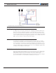
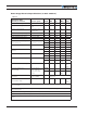
Command, I/O and Sensor Signals Specifications
TABLE 9.
Parameter Measure point Min Typ Max Units
Main 5V Output Voltage Ground to 5V pins on 4.6 4.75 4.9 Volts
5V Output Current 5V pins on RJ45 and DSub15 200 (1) mA
Digital Output Voltage Ground to Output pins 30 Volts
Output On resistance Output pin to ground 0.25 0.5 Ohm
Output Short circuit threshold Output pin 1. 7 3.5 Amps
Digital Output Current Output pins, sink current 1. 5 Amps
Input Impedances (except
DIN11-19)
AIN/DIN Input to Ground 53 kOhm
Digital Input 0 Level Ground to Input pins -1 1 Volts
Digital Input 1 Level Ground to Input pins 3 30 Volts
Analog Input Range Ground to Input pins 0 5.1 Volts
Analog Input Precision Ground to Input pins 0.5 %
Analog Input Resolution Ground to Input pins 1 mV
Encoder Frequency 500 kHz
Pulse durations Pulse inputs 20000 10 us
Pulse repeat rate Pulse inputs 50 250 Hz
Pulse Capture Resolution Pulse inputs 1 us
Frequency Capture Pulse inputs 100 1000 Hz
Note 1: Sum of all 5VOut outputs
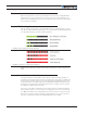
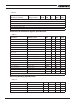
Operating & Timing Specifications
TABLE 10.
Parameter Measure Point Min Typ Max Units
Command Latency Command to output change 0 0.5 1 ms
PWM Frequency Motor Output 10 18 20 kHz
Closed Loop update rate Internal 1000 Hz
RS232 baud rate Rx & Tx pins 115200 (1) Bits/s
Electrical Specifications