
User's Manual
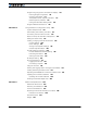


AX3500 Quick Start
16 AX3500 Motor Controller User’s Manual Version 1.9b. June 1, 2007
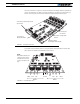
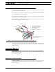
The front side (shown in Figure 1) contains the buttons and display needed to operate and
monitor the controller. The 15-pin connector provides the connection to the R/C radio, joy-
stick or microcomputer, as well as connections to optional switches and sensors.
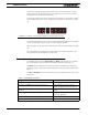
At the back of the controller (shown in the figure below) are located all the Fast-on tabs
that must be connected to the batteries and the motors.
Connector to Receiver/Controls
and sensors
Operating Status
and Program LED Display
Controller Configuration
buttons
FIGURE 1. Controller Front View
Connector to
Optical Encoders
RC Outputs
connectors
VMot
Motor 2 Motor 1
M2+ M1+ M1- VMotM2- 3 x Gnd
Pwr
Ctrl
FIGURE 2. Controller Rear View
Note:
Both VMot tabs are con-
nected to each other in
the board and must be
wired to the same volt-
age.