AX1500 Dual Channel Digital Motor Controller User’s Manual v1.9b, June 1, 2007 visit www.roboteq.com to download the latest revision of this manual ©Copyright 2003-2007 Roboteq, Inc.
AX1500 Motor Controller User’s Manual Version 1.9b.
Revision History Revision History Date Version Changes June 1, 2007 1.
AX1500 Motor Controller User’s Manual Version 1.9b.
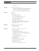
Revision History 3 SECTION 1 Important Safety Warnings 13 This product is intended for use with rechargeable batteries 13 Avoid Shorts when Mounting Board against Chassis 13 Do not Connect to a RC Radio with a Battery Attached 13 Beware of Motor Runaway in Improperly Closed Loop 13 SECTION 2 AX1500 Quick Start 15 What you will need 15 Locating the Connectors 15 Connecting to the Batteries and Motors 17 Connecting to the 15-pin Connector Connecting the R/C Radio 18 19 Powering On the Controller 2
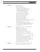
SECTION 5 General Operation 39 Basic Operation 39 Input Command Modes 39 Selecting the Motor Control Modes 40 Open Loop, Separate Speed Control 40 Open Loop, Mixed Speed Control 40 Closed Loop Speed Control 41 Close Loop Position Control 41 User Selected Current Limit Settings 42 Temperature-Based Current Limitation Battery Current vs.
Recommended Encoder Types 68 Installing the Encoder Module 69 Connecting the Encoder 70 Cable Length and Noise Considerations 71 Motor - Encoder Polarity Matching 72 Voltage Levels, Thresholds and Limit Switches Wiring Optional Limit Switches 73 Wiring Limit Switches Without Encoders Effect of Limit Switches 72 75 75 Using the Encoder Module to Measure Distance 76 Using the Encoder to Measure Speed 76 Using the Encoder to Track Position 77 RS232 Communication with the Encoder Module Encoder Test
Adjust Offset and Max Speed 96 Control Loop Description 96 PID tuning in Speed Mode SECTION 10 97 Normal and Fault Condition LED Messages 99 Power On LED 99 Diagnostic LED 99 Normal Operation Flashing Pattern 99 Output Off / Fault Condition 100 SECTION 11 R/C Operation 101 Mode Description 101 Selecting the R/C Input Mode 102 Connector I/O Pin Assignment (R/C Mode) 102 R/C Input Circuit Description 103 Supplied Cable Description 103 Powering the Radio from the controller 104 Connecting to a S
Connector I/O Pin Assignment (RS232 Mode) 122 Cable configuration 123 Extending the RS232 Cable 123 Communication Settings 124 Establishing Manual Communication with a PC 124 RS232 Communication with the Encoder Module 125 Entering RS232 from R/C or Analog mode 126 Data Logging String in R/C or Analog mode 126 RS232 Mode if default 127 Commands Acknowledge and Error Messages 127 Character Echo 127 Command Acknowledgement 127 Command Error 127 Watchdog time-out 127 RS-232 Watchdog 128 Controller Commands a
Controller Identification Register 144 Current Amps Limit Registers 144 RS232 Encoder Command Set 145 Read Encoder Counter 145 Set/Reset Encoder Counters and Destination Registers 145 Read Speed 146 Read Distance 147 Read Speed/Distance 147 Read Encoder Limit Switch Status 147 Read / Modify Encoder Module Registers and Parameters 148 Register Description 150 Encoder Hardware ID code 150 Switch Status 150 Speed or Distance 1 or 2 150 Counter Read/Write Mailbox 151 Counter 1 and 2 151 Destination Register 1 a
Logging Data to Disk 173 Connecting a Joystick 174 Using the Console 174 Viewing and Logging Data in Analog and R/C Modes 176 Loading and Saving Profiles to Disk 176 Operating the AX1500 over a Wired or Wireless LAN 176 Updating the Controller’s Software 178 Updating the Encoder Software 178 Creating Customized Object Files SECTION 15 Mechanical Specifications Mechanical Dimensions 179 181 181 Mounting Considerations 182 Thermal Considerations 182 Attaching the Controller Directly to a Chassis Prec
AX1500 Motor Controller User’s Manual Version 1.9b.
SECTION 1 Important Safety Warnings Read this Section First The AX1500 is a high power electronics device. Serious damage, including fire, may occur to the unit, motors, wiring and batteries as a result of its misuse. Transistors may explode and require the use of safety glasses when operated in direct view. Please review the User’s Manual for added precautions prior to applying full battery or full load power.
Important Safety Warnings 14 AX1500 Motor Controller User’s Manual Version 1.9b.
SECTION 2 AX1500 Quick Start This section will give you the basic information needed to quickly install, setup and run your AX1500 controller in a minimal configuration.
AX1500 Quick Start The front side (shown in Figure 1) contains the Power/Status LED and the 15-pin connector to the R/C radio, joystick or microcomputer, as well as connections to optional switches and sensors. Connector to Receiver/Controls and sensors Power LED Status LED FIGURE 1. AX1500 Controller Front View At the back of the controller (shown in the figure below) are located all the terminals that must be connected to the batteries and the motors.
Connecting to the Batteries and Motors Connecting to the Batteries and Motors Connection to the batteries and motors is shown in the figure below and is done by connecting wires to the controller’s terminal strip. Motor2 Optional Diode Power switch + Fuse On - Off + - Optional Emergency Disconnect VMot M1M1+ PwrCtrl GND GND GND M2M2+ VMot Motor1 Controller 12V to 24V Motor Battery Notes: - The Battery Power connection are doubled in order to provide the maximum current to the controller.
AX1500 Quick Start Important Warning Do not rely on cutting power to the controller for it to turn off if the Power Control is left floating. If motors are spinning because the robot is pushed are pushed or because of inertia, they will act as generators and will turn the controller, possibly in an unsafe state. ALWAYS ground the Power Control wire to turn the controller Off and keep it Off. Important Warning The controller includes large capacitors.
Connecting the R/C Radio Connecting the R/C Radio Connect the R/C adapter cables to the controller on one side and to two or three channels on the R/C receiver on the other side. If present, the third channel is for activating the accessory outputs and is optional. When operating the controller in “Separate” mode, the wire labelled Ch1 controls Motor1, and the wire labelled Ch2 controls Motor2.
AX1500 Quick Start Powering On the Controller Important reminder: There is no On-Off switch on the controller. You must insert a switch on the controller’s power terminal as described in section“Connecting to the Batteries and Motors” on page 17. To power the controller, center the joystick and trims on the R/C transmitter. In Analog mode, center the command potentiomenter or joystick.Then turn on the switch that you have placed on the on the Power Control input.
Connecting the controller to your PC using Roborun Connecting the controller to your PC using Roborun Connecting the controller to your PC is not necessary for basic R/C operation.
AX1500 Quick Start The intuitive Graphical User Interface will let you view and change any of the controller’s parameters. The “Run” tab will present a number of buttons, dials and charts that are used for operating and monitoring the motors. Obtaining the Controller’s Software Revision Number One of the unique features of the AX1500 is the ability to easily update the controller’s operating software with new revisions downloaded from Roboteq’s web site at www.roboteq.com.
SECTION 3 AX1500 Motor Controller Overview Congratulations! By selecting Roboteq’s AX1500 you have empowered yourself with the industry’s most versatile, and programmable DC Motor Controller for mobile robots. This manual will guide you step by step through its many possibilities. Product Description The AX1500 is a highly configurable, microcomputer-based, dual-channel digital speed or position controller with built-in high power drivers.
AX1500 Motor Controller Overview The motors are driven using high-efficiency Power MOSFET transistors controlled using Pulse Width Modulation (PWM) at 16kHz. The AX1500 power stages can operate from 12 to 40VDC and can sustain up to 30A of controlled current, delivering up to 1200W (approximately 1.5 HP) of useful power to each motor. The many programmable options of the AX1500 are easily configured using the supplied PC utility.
Technical features • • • • • Potentiometer input for position while in analog command mode User defined purpose (RS232 mode only) One Switch input configurable as • • • • • User defined purpose (RS232 mode only) 2 Extra analog inputs.
AX1500 Motor Controller Overview • • • • • • 20A extended High current operation may be extended with forced cooling 125A peak Amps per channel 16kHz Pulse Width Modulation (PWM) output Auxiliary output for brake, clutch or armature excitation Heat sink on PCB Advanced Safety Features • • • Safe power on mode • • • Overvoltage and Undervoltage protection • • • • Diagnostic LED Optical isolation on R/C control inputs Automatic Power stage off in case of electrically or software induced program fai
Power Connections SECTION 4 Connecting Power and Motors to the Controller This section describes the AX1500 Controller’s connections to power sources and motors. Important Warning Please follow the instructions in this section very carefully. Any problem due to wiring errors may have very serious consequences and will not be covered by the product’s warranty. Power Connections The AX1500 has three Ground, two Vmot terminals and a Power Control terminal.
Connecting Power and Motors to the Controller Note: Both VMot terminals are connected to each other in the board and must be wired to the same voltage. VMot M2+ M2- 3 x Gnd Motor 2 Pwr Ctrl M1+ M1- VMot Motor 1 FIGURE 7. Controller Rear View and Power Connector Tabs Controller Power The AX1500 uses a flexible power supply scheme that is best described in Figure 8. In this diagram, it can be seen that the power for the Controller’s microcomputer is separate from this of the motor drivers.
Controller Power Mot1(-) Mot1(+) 5Vmin 40V max Channel 1 MOSFET Power Stage 9.5V min 13V max DC/DC 10.5V min 40V max Channel 2 MOSFET Power Stage GND Power Control &Backup ENABLE Microcomputer & MOSFET Drivers VBatt Vmot GND 5Vmin 40V max GND VBatt Vmot Mot2(+) Mot2(-) FIGURE 8. Representation of the AX1500’s Internal Power Circuits When powered only via the Power Control input, the controller will turn On but motors will not be able to turn until power is also present on the VMot terminals.
Connecting Power and Motors to the Controller TABLE 2. Controller Status depending on Power Control and VMot Power Control input is connected to And Main Battery Voltage is Action 10.5V to 40V 0V Controller is On. 10.5V to 40V 1V to 40V Controller is On. Power Stage is Off Power Stage is Active All 3 ground (-) are connected to each other inside the controller. The two main battery wires are also connected to each other internally.
Controller Powering Schemes There is no need to insert a separate switch on Power cables, although for safety reasons, it is highly recommended that a way of quickly disconnecting the Motor Power be provided in the case of loss of control and all of the AX1500 safety features fail to activate. The two VMot terminals are connected to each other inside the controller. The same is true for the Ground Terminals. You should wire each pair together as shown in the diagram above.
Connecting Power and Motors to the Controller Motor2 Power switch + On - Off + - VMot M1M1+ PwrCtrl GND GND GND M2M2+ VMot Motor1 Controller 12V to 40V 12V to 40V Motor Battery Backup Battery FIGURE 10. Powering the AX1500 with a Main and Backup Supply Important Warning Unless you can ensure a steady 12V to 40V voltage in all conditions, it is recommended that the battery used to power the controller’s electronics be separate from the one used to power the motors.
Single Channel Operation If you are using this type of motor, make sure that it is mounted on isolators and that its casing will not cause a short circuit with other motors and circuits which may also be inadvertently connected to the same metal chassis. Single Channel Operation The AX1500’s two channel outputs can be paralleled as shown in the figure below so that they can drive a single load with twice the power.
Connecting Power and Motors to the Controller It will be safe to wire in parallel the controller’s outputs only after you have verified that both outputs react identically to channel 1 commands. Xilinx MCU Jumper In for Single Channel FIGURE 12. AX1500 Jumper setting for Single Channel Operation Power Fuses For low Amperage applications (below 30A per motor), it is recommended that a fuse be inserted in series with the main battery circuit as shown in the Figure 9 on page 30.
Electrical Noise Reduction Techniques be amplified beyond the controller’s capability to correct them. This is particularly the case for the main battery power wires. Important Warning Avoid using long cable lengths (beyond 2 feet) from the main power battery to the controller as the added inductance may cause damage to the controller when operating at high currents. Try extending the motor wires instead since the added inductance is less harmful on this side of the controller.
Connecting Power and Motors to the Controller Please download the Application Note “Understanding Regeneration” from the www.roboteq.com for an in-depth discussion of this complex but important topic. Important Warning Use the AX1500 only with a rechargeable battery as supply to the Motor Power wires (VMot terminals). If a transformer or power supply is used, damage to the controller and/or power supply may occur during regeneration. See “Using the Controller with a Power Supply” on page 36 for details.
Using the Controller with a Power Supply • Use a power supply that will not suffer damage in case a voltage is applied at its output that is higher than the transformer’s own output voltage. This information is seldom published in commercial power supplies, so it is not always possible to obtain positive reassurance that the supply will survive such a condition. • Avoid deceleration that is quicker than the natural deceleration due to the friction in the motor assembly (motor, gears, load).
Connecting Power and Motors to the Controller 38 AX1500 Motor Controller User’s Manual Version 1.9b.
Basic Operation General Operation SECTION 5 This section discusses the controller’s normal operation in all its supported operating modes.
General Operation Selecting the Motor Control Modes For each motor, the AX1500 supports multiple motion control modes. The controller’s factory default mode is Open Loop Speed control for each motor. The mode can be changed using any of the methods described in “Loading, Changing Controller Parameters” on page 164. Open Loop, Separate Speed Control In this mode, the controller delivers an amount of power proportional to the command information. The actual motor speed is not measured.
Selecting the Motor Control Modes Controller FIGURE 14. Effect of commands to motors examples in mixed mode Closed Loop Speed Control In this mode, illustrated in Figure 16, an analog tachometer or an optical encoder is used to measure the actual motor speed. If the speed changes because of changes in load, the controller automatically compensates the power output. This mode is preferred in precision motor control and autonomous robotic applications.
General Operation Position Feedback Position Sensor Gear box FIGURE 16. Motor with potentiometer assembly for Position operation User Selected Current Limit Settings The AX1500 has current sensors at each of its two output stages. Every 16 ms, this current is measured and a correction to the output power level is applied if higher than the user preset value. The current limit may be set using the supplied PC utility. Using the PC utility is it possible to set the limit with a 0.25A granularity from 3.
Battery Current vs. Motor Current The numbers in the table are the max Amps allowed by the controller at a given temperature point. If the Amps limit is manually set to a lower value, then the controller will limit the current to the lowest of the manual and temperature-adjusted max values. This capability ensures that the controller will be able to work safely with practically all motor types and will adjust itself automatically for the various load and environmental conditions.
General Operation Vbat On Motor Off FIGURE 17. Current flow during operation On Off I mot Avg I bat Avg FIGURE 18. Instant and average current waveforms The relation between Battery Current and Motor current is given in the formula below: Motor Current = Battery Current / PWM Ratio Example: If the controller reports 10A of battery current while at 10% PWM, the current in the motor is 10 / 0.1 = 100A. Important Warning Do not connect a motor that is rated at a higher current than the controller.
Programmable Acceleration Programmable Acceleration When changing speed command, the AX1500 will go from the present speed to the desired one at a user selectable acceleration. This feature is necessary in order to minimize the surge current and mechanical stress during abrupt speed changes. This parameter can be changed by using the controller’s front switches or using serial commands.
General Operation TABLE 4. Acceleration setting table Acceleration Setting Using RS232 Acceleration Setting Using Switches %Acceleration per 16ms Time from 0 to max speed 15 Hex - 17.97% 0.089 second 05 Hex 5 18.75% 0.085 second Important Warning Depending on the load’s weight and inertia, a quick acceleration can cause considerable current surges from the batteries into the motor. A quick deceleration will cause an equally large, or possibly larger, regeneration current surge.
Left / Right Tuning Adjustment % Forward (Motor Output) 100 80 Logarithmic Strong Logarithmic Weak 60 Linear (default) Exponential Weak Exponential Strong 100 80 60 20 0 40 - 20 - 40 - 60 20 - 80 - 100 40 % Command Input 20 Deadband 40 60 80 100 % Reverse FIGURE 19. Exponentiation curves The AX1500 is delivered with the “linear” curves selected for both joystick channels.
General Operation is found on all R/C transmitters, and which is actually an offset correction, the Left/Right Adjustment is a true multiplication factor as shown in Figure 20 100 80 60 60 40 40 20 40 40 60 60 80 5.25% 3% 100 % Reverse 0% % Forward (Motor Output) 100 80 0 20 60 % Command Input - 20 - 40 - 60 20 - 80 - 100 100 80 60 20 0 40 - 20 - 40 - 60 - 80 20 40 80 - 100 % Forward (Motor Output) 0% -3% -5.
Activating Brake Release or Separate Motor Excitation TABLE 6. Left/Right Adjustment Parameter selection Parameter Value Speed Adjustment Parameter Value Speed Adjustment 5 -1.5% 12 4.5% 6 -0.75% 14 5.25% Activating Brake Release or Separate Motor Excitation The controller may be configured so that the Output C will turn On whenever one of the two motors is running. This feature is typically used to activate the mechanical brake release sometimes found on motors for personal mobility systems.
General Operation Special Use of Accessory Digital Inputs The AX1500 includes two general purpose digital inputs identified as Input E and Input F. When an Encoder Module is installed, input E is disabled. The location of these inputs on the DB15 connector can be found in the section “I/O List and Pin Assignment” on page 54, while the electrical signal needed to activate them is shown on “Connecting Switches or Devices to Input F” on page 56. By default, these inputs are ignored by the controller.
AX1500 Connections SECTION 6 Connecting Sensors and Actuators to Input/Outputs This section describes the various inputs and outputs and provides guidance on how to connect sensors, actuators or other accessories to them. AX1500 Connections The AX1500 uses a set of power wires (located on the back of the unit) and a DB15 connector for all necessary connections. The diagram on the figure below shows a typical wiring diagram of a mobile robot using the AX1500 controller.
Connecting Sensors and Actuators to Input/Outputs 2 4 1 5 3 3 6 7 9 8 1- DC Motors 2- Optional sensors: - Tachometers (Closed loop Speed mode) - Potentiometers (Servo mode) - Encoders when Module present 3- Motor Power supply wires 4- Power Control wire5- Controller 6- R/C Radio Receiver, microcomputer, or wireless modem 7- Command: RS-232, R/C Pulse 8- Miscellaneous I/O 9- Running Inverted, or emergency stop switch FIGURE 21.
AX1500’s Inputs and Outputs When the controller operates in modes that do not use these I/O, these signals become available for user application. Below is a summary of the available signals and the modes in which they are used by the controller or available to the user. TABLE 7.
Connecting Sensors and Actuators to Input/Outputs I/O List and Pin Assignment The figure and table below lists all the inputs and outputs that are available on the AX1500. 9 15 Pin1 8 FIGURE 22. Controller’s DB15 connector pin numbering TABLE 8.
Connecting devices to Output C TABLE 8.
Connecting Sensors and Actuators to Input/Outputs Important warning: Overvoltage spikes induced by switching inductive loads, such as solenoids or relays, will destroy the transistor unless a protection diode is used. Connecting Switches or Devices to Input E Input E is a general purpose, digital input. This input is only available if no encoder module is present and is active when in the RS232 and Analog modes. In R/C mode, this line is used as the radio channel 3 input.
Connecting Switches or Devices to EStop/Invert Input +5V Out 14 +5V Out 14 +5V In 7 10kOhm Input F 4 10kOhm 10kOhm Input F 4 +5V In 7 Internal Buffer GND In 6 Internal Buffer 10kOhm GND In 6 GND Out 5 GND Out 5 FIGURE 25. Switch wiring to Input F The status of Input F can be read in the RS232 mode with the ?i command string. The controller will respond with three sets of 2 digit numbers.
Connecting Sensors and Actuators to Input/Outputs +5V 14 AX2500 Internal Buffer and Resistor 10kOhm Input EStop/Inv 15 Ground 5 FIGURE 26. Emergency Stop / Invert switch wiring The status of the EStop/Inv can be read at all times in the RS232 mode with the ?i command string. The controller will respond with three sets of 2 digit numbers. The status of the ES/Inv Input is contained in the last set of numbers and may be 00 to indicate an Off state, or 01 to indicate an On state.
Connecting Tachometer to Analog Inputs Connecting the potentiometer to the controller is as simple as shown in the diagram on Figure 28. +5V 14 Ana 1: Ana 2: Ana 3: Ana 4: 11 10 12 8 Internal Resistors and Converter 47kOhm A/D 10kOhm 10kOhm 47kOhm Ground 5 FIGURE 28. Potentiometer wiring in Position mode The potentiometer must be attached to the motor frame so that its body does not move in relationship with the motor. The potentiometer axle must be firmly connected to the gear box output shaft.
Connecting Sensors and Actuators to Input/Outputs Since the controller only accepts a 0 to 5V positive voltage as its input, the circuit shown in Figure 29 must be used between the controller and the tachometer: a 10kOhm potentiometer is used to scale the tachometer output voltage to -2.5V (max reverse speed) and +2.5V (max forward speed). The two 1kOhm resistors form a voltage divider that sets the idle voltage at mid-point (2.5V), which is interpreted as the zero position by the controller.
Connecting External Thermistor to Analog Inputs Connecting External Thermistor to Analog Inputs Using external thermistors, the AX1500 can be made to supervise the motor’s temperature and adjust the power output in case of overheating. Connecting thermistors is done according to the diagram show in Figure 30. The AX1500 is calibrated using a 10kOhm Negative Coefficient Thermistor (NTC) with the temperature/resistance characteristics shown in the table below. TABLE 11.
Connecting Sensors and Actuators to Input/Outputs 100 Analog Input Reading 50 0 -50 -100 11 0 10 0 90 80 70 60 50 40 30 20 10 0 -1 0 -2 0 -150 Temperature in Degrees C FIGURE 31. Signed binary reading by controller vs. NTC temperature To read the temperature, use the ?p command to have the controller return the A/D converter’s value. The value is a signed 8-bit hexadecimal value. Use the chart data to convert the raw reading into a temperature value.
Connecting User Devices to Analog Inputs Measured volts = ((controller reading + 128) * 0.255) -5 Note: The A/D converter’s reading is returned by the ?p command and is a signed 8-bit hexadecimal value. You must add 128 to bring its range from -127/+127 to 0/255. Connecting User Devices to Analog Inputs The two analog inputs can be used for any other purpose. The equivalent circuit for each input is shown in Figure 33.
Connecting Sensors and Actuators to Input/Outputs These sensors are used to automatically reduce the maximum Amps that the controller can deliver as it overheats. However, the temperature can be read using the RS232 port using the ?m query, or during data logging (see “Analog and R/C Modes Data Logging String Format” on page 156) The analog value that is reported will range from 0 (warmest) to 255 (coldest).
Internal Heatsink Temperature Sensors else { LoTemp = i * 5 - 40; HiTemp = LoTemp + 5; lobound = TempTable[i]; hibound = TempTable[i+1]; temp = LoTemp + (5 * ((AnaValue - lobound)*100/ (hibound - lobound)))/100; return temp; } } AX1500 Motor Controller User’s Manual 65
Connecting Sensors and Actuators to Input/Outputs 66 AX1500 Motor Controller User’s Manual Version 1.9b.
Optical Incremental Encoders Overview SECTION 7 Installing, Connecting and Using the Encoder Module This section describes the Encoder input module that may be added to the AX1500. Optical Incremental Encoders Overview Optical incremental encoders are a means for capturing speed and travelled distance on a motor. Unlike absolute encoders which give out a multi-bit number (depending on the resolution), incremental encoders output pulses as they rotate.
Installing, Connecting and Using the Encoder Mod- A Channel 1 Pulse = 4 Transitions = 4 Counts B Channel Quadrature Signal Count Down Count Up FIGURE 35. Quadrature encoder output waveform The figure below shows the typical construction of a quadrature encoder. As the disk rotates in front of the stationary mask, it shutters light from the LED. The light that passes through the mask is received by the photo detectors.
Installing the Encoder Module Specifically, the encoder module can process 250,000 counts per seconds. As discussed in the previous section, a count is generated for each transition on the Channel A and Channel B. Therefore the module will work with encoders outputting up to 62,500 pulses per second. Commercial encoders are rated by their numbers of “Pulses per Revolution” (also sometimes referred as “Cycles per Revolution).
Installing, Connecting and Using the Encoder Mod- 2- Carefully insert the encoder module on top of the two headers present on the controller’s main board and shown in Figure 38. Beware that the two matting connectors are precisely aligned. 3- The encoder module will be held in place by the headers and connectors. For use in FIGURE 38. Position of Encoder Module on Controller’s main board harsh shock and vibration environments, solder a metal wire inside the 0.
Cable Length and Noise Considerations 1 8 8 1 FIGURE 40. Encoder connector TABLE 12. Encoder Connector Pinout Cable Color Pin Name (when using standard network cable) 1 Encoder 2 - Channel B. Optional Limit Switch 4 Orange/White 2 Encoder 2 - Channel A. Optional Limit Switch 3 Orange 3 Ground (same as pin 7) Green/White 4 5V Out (same as pin 8) Blue 5 Encoder 1 - Channel B. Optional Limit Switch 2 Blue/White 6 Encoder 1 - Channel A.
Installing, Connecting and Using the Encoder Mod- Important Warning Excessive cable length will cause electrical noise to be captured by the controller and cause erratic functioning that may lead to failure. In such situation, stop operation immediately. Motor - Encoder Polarity Matching When using the Encoder module for closed loop speed control, it is imperative that when the motor is turning in the forward direction, the counter increments its value and a positive speed value is measured.
Wiring Optional Limit Switches 2.5V Signal on Channel A or B 0.5V Quadrature Signal Switch Detect Signal (Not meaningful) FIGURE 42. Signals seen by encoder using direct connection and no limit switches In Figure 42, the encoder and switches are wired to the encoder module using a set of resistors designed to create a multi-level signal combining both pieces of information. Details on the necessary wiring is provided in the next section.
Installing, Connecting and Using the Encoder Mod- 5V Out 4.7kOhm 4.7kOhm 1kOhm 5V Ch A In Ch A Encoder GND Encoder Module Ch B Ch B In 1kOhm SW1 SW2 GND FIGURE 44. Signals seen by encoder using multi-levels and limit switches Using this circuit when the switch is open, a 0V (low-level) output from the encoder goes through a 1k and 4.7k voltage divider, thus creating a voltage that will never be below 0.8V at the encoder module’s input.
Wiring Limit Switches Without Encoders Wiring Limit Switches Without Encoders If no encoder is used, the Encoder Module’s inputs can be used to wire limit switches directly with solely a pull-up resistor as shown in the diagram below. 5V Out 4.7kOhm 4.7kOhm 4.7kOhm 4.7kOhm Ch B In SW1 SW2 SW3 8-4 5 Ch A In 6 Ch B In 1 Ch A In 2 Encoder Input SW4 GND 7-3 FIGURE 45.
Installing, Connecting and Using the Encoder Mod- TABLE 14. Effects of Limit Switches 3 and 4 on Motor 2 SW3 SW4 Motor 2 Fwd Motor 2 Rev OFF ON Allowed Stopped ON ON Stopped Stopped In Single Channel Mode, limit switches 3 and 4 are used. This is to allow direct connection of an encoder on the inputs for channel 1 and direct connection of switches on the inputs for channel 2 TABLE 15.
Using the Encoder to Track Position A simple procedure is included in the Roborun PC utility to easily determine and set these parameters. For information, the exact formula is shown below: Measured Speed Value = RPM * PPR * 4 * (Time Base+1) * 256 / (60 * 1000000) or Measured Speed Value = RPM * PPR * (Time Base + 1) / 58593.
Installing, Connecting and Using the Encoder Mod- The actual formula is as follows: Distance = (Destination - Counter value) / Divider Where: divider is a configurable parameter of value 1, 2, 4, 8, 16, 32, 64 or 127 If computed distance is less than -127, then reported distance is -127 If computed distance is larger than +127, then reported distance is +127 Destination= 50,050 Counter= 50,000 distance 50 25 12 6 3 1 0 0 at divider 1 2 4 8 16 32 64 128 FIGURE 46.
Encoder Testing and Setting Using the PC Utility Encoder Testing and Setting Using the PC Utility Extensive diagnostic, calibration, setting and testing support is provided in the Roborun PC utility. Basic instructions on how to install and run the PC utility can be found in “Encoder Setting and Testing” on page 168.
Installing, Connecting and Using the Encoder Mod- 80 AX1500 Motor Controller User’s Manual Version 1.9b.
Mode Description Closed Loop Position Mode SECTION 8 This section describes the AX1500 Position mode, how to wire the motor and position sensor assembly and how to tune and operate the controller in this mode. Mode Description In this mode, the axle of a geared-down motor is coupled to a position sensor that is used to compare the angular position of the axle versus a desired position. The controller will move the motor so that it reaches this position.
Closed Loop Position Mode Position Sensor Selection The AX1500 may be used with the following kind of sensors: • • • Potentiometers Hall effect angular sensors Optical Encoders (with Encoder Module) The first two are used to generate an analog voltage ranging from 0V to 5V depending on their position. They will report an absolute position information at all times. Optical encoders report incremental changes from a reference which is their initial position when the controller is powered up or reset.
Feedback Potentiometer wiring The mechanical coupling between the motor and the sensor must be as tight as possible. If the gear box is loose, the positioning will not be accurate and will be unstable, potentially causing the motor to oscillate. Some sensor, such as potentiometers, have a limited rotation range of typically 270 degrees (3/4 of a turn), which will in turn limit the mechanical motion of the motor/potentiometer assembly.
Closed Loop Position Mode 14 2k - 10k +5V 2k - 10k Feedback 1 Feedback 2 5 Ground 11 Ana1 10 Ana2 12 Ana3* 8 Ana4* FIGURE 49. Pot wiring for RS232 or RC Command and Analog Feedback Feedback Potentiometer wiring in Analog Mode When the controller is configured in Analog mode, the analog inputs 1 and 2 are used for commands while the analog inputs 3 and 4 are used for feedback.
Analog Feedback on Single Channel Controllers Analog Feedback on Single Channel Controllers On Single Channel controllers (SC Version - not to be confused with Dual Channel controllers of which only one channel is used for position control - See “Single Channel Operation” on page 177.), the controller accepts one command and uses one input for feedback.
Closed Loop Position Mode This wiring is also the one to use when the controller is in Analog mode but switched to RS232 after reset using the method discussed in “Entering RS232 from R/C or Analog mode” on page 126 Using Optical Encoders in Position Mode The AX2550 and AX1500 may be equipped with an optional Optical Encoder Module. Optical Encoders require special handling. See Figure 7, “Installing, Connecting and Using the Encoder Module,” on page 67 for a detailed discussion.
Encoder Error Detection and Protection 10. If the motor turns in the direction away from the sensor, then the polarity is reversed. The wire polarity on the motors should be exchanged. If using a potentiometer as sensor, the GND and +5V wires on the potentiometer may be swapped instead. If using an Optical Encoder, ChA and ChB outputs can be swapped. 11. Move the sensor back to the center point to stop the motor. Cut the power if control is lost. 12.
Closed Loop Position Mode The diode polarity depends on the particular wiring and motor orientation used in the application. If the diode is mounted backwards, the motor will not stop once the limit switch lever is pressed. If this is the case, reverse the diode polarity. The diodes may be eliminated, but then it will not be possible for the controller to move the motor once either of the limit switches has been triggered.
Using Current Limiting as Protection Manual Emergency Stop Switch SW1 SW2 Motor Ground Controller Emergency Stop Input FIGURE 54. Safety limit using AX1500’s Emergency Stop input Important Warning Limit switches must be used when operating the controller in Position Mode. This will significantly reduce the risk of mechanical damage and/or injury in case of damage to the position sensor or sensor wiring.
Closed Loop Position Mode A higher Proportional Gain will cause the algorithm to apply a higher level of power for a given measured error, thus making the motor move quicker. Because of inertia, however, a faster moving motor will have more difficulty stopping when it reaches its desired position. It will therefore overshoot and possibly oscillate around that end position.
PID tuning in Position Mode The Roborun PC utility makes this experimentation easy by providing one screen for changing the Proportional, Integral and Differential gains and another screen for running and monitoring the motors. When tuning the motor, first start with the Integral Gain at zero, increasing the Proportional Gain until the motor overshoots and oscillates. Then add Differential gain until there is no more overshoot. If the overshoot persists, reduce the Proportional Gain.
Closed Loop Position Mode 92 AX1500 Motor Controller User’s Manual Version 1.9b.
Mode Description Closed Loop Speed Mode SECTION 9 This section discusses the AX1500 Close Loop Speed mode. Mode Description In this mode, an analog or digital speed sensor measures the actual motor speed and compares it to the desired speed. If the speed changes because of changes in load, the controller automatically compensates the power output. This mode is preferred in precision motor control and autonomous robotic applications.
Closed Loop Speed Mode Detailed information on how to install and wire optical encoders is provided at “Installing, Connecting and Using the Encoder Module” on page 67. If using optical encoders, omit the Analog Tachometer discussion in this section and resume reading from “Control Loop Description” on page 96. Optical Encoders require special handling. See “Installing, Connecting and Using the Encoder Module” on page 67 for a detailed discussion.
Speed Sensor and Motor Polarity Speed Sensor and Motor Polarity The tachometer or encoder polarity (i.e. which rotation direction produces a positive of negative speed information) is related to the motor’s rotation speed and the direction the motor turns when power is applied to it. In the Closed Loop Speed mode, the controller compares the actual speed, as measured by the tachometer, to the desired speed.
Closed Loop Speed Mode Adjust Offset and Max Speed For proper operation, the controller must see a 0 analog speed value (2.5V voltage on the analog input). To adjust the 0 value when the motors are stopped, use the Roborun utility to view the analog input value while the tachometer is not turning. Move the 0 offset potentiometer until a stable 0 is read. This should be right around the potentiometer’s middle position.
PID tuning in Speed Mode The Differential component of the algorithm computes the changes to the error from one 16 ms time period to the next. This change will be a relatively large number every time an abrupt change occurs on the desired speed value or the measured speed value. The value of that change is then multiplied by a user selectable Differential Gain and added to the output.
Closed Loop Speed Mode In Speed Mode, the Integral component of the PID is the most important and must be set first. The Proportional and Differential component will help improve the response time and loop stability. In the case where the load moved by the motor is not fixed, tune the PID with the minimum expected load and tune it again with the maximum expected load. Then try to find values that will work in both conditions.
Power On LED Normal and Fault Condition LED Messages SECTION 10 This section discusses the meaning of the various messages and codes that may be displayed on the LED display during normal operation and fault conditions. Power On LED The AX1500 features an LED that comes on whenever the board is powered on. When lit, this LED indicates that the on-board DC/DC converter is functioning. It provides no information regarding the controller’s operation.
Normal and Fault Condition LED Messages RC Mode RS232 Mode No Watchdog RS232 Mode with Watchdog Analog Mode FIGURE 59. Status LED Flashing pattern during normal operation Output Off / Fault Condition The controller LED will tun On solid to signal that the output stage is off as a result of a any of the recoverable conditions listed below. Temporary Fault Permanent Error FIGURE 60.
Mode Description SECTION 11 R/C Operation This section describes the controller’s wiring and functions specific to the R/C radio control mode. Mode Description The AX1500 can be directly connected to an R/C receiver. In this mode, the speed or position information is contained in pulses whose width varies proportionally with the joysticks’ positions. The AX1500 mode is compatible with all popular brands of R/C transmitters.
R/C Operation Selecting the R/C Input Mode The R/C Input Mode is the factory default setting. If the controller has been previously set to a different Input Mode, it will be necessary to reset it to the R/C mode using the serial port and the PC utility. See “Using the Roborun Configuration Utility” on page 161, and “Accessing & Changing Configuration Parameter in Flash” on page 133 Connector I/O Pin Assignment (R/C Mode) 9 15 Pin1 8 FIGURE 62.
R/C Input Circuit Description TABLE 16. Connector pin-out in R/C mode Pin Number Input or Output 14 15 Signal Description Power Out +5V +5V Power Output (100mA max.) Input Input EStop/Inv Emergency Stop or Invert Switch input R/C Input Circuit Description The AX1500 R/C inputs are directly connected to the MCU logic. Figure 63 shows an electrical representation of the R/C input circuit.
R/C Operation 1 2 3 1 8 9 15 FIGURE 64. RC Cable wiring diagram 3 2 1 . FIGURE 65. RC connection cable Powering the Radio from the controller The 5V power and ground signals that are available on the controller’s connector may be used to power the R/C radio. The wire loop is used to bring the controller’s power to the the radio as well as for powering the optocoupler stage. Figure 66 below shows the connector wiring necessary to do this. Figure 67 shows the equivalent electrical diagram.
Powering the Radio from the controller Channel 3 Channel 2 3: 4: 6: 7: 8: Channel 1 Channel 1 Command Pulses Channel 2 Command Pulses Radio battery (-) Ground Radio battery (+) Channel 3 Command Pulses 8 9 Pin 1 Wire loop bringing power from controller to RC radio 15 FIGURE 66. Wiring for powering R/C radio from controller 14 Controller Power R/C Radio Power 7 R/C Radio R/C Channel 1 3 R/C Channel 2 4 R/C Channel 3 8 R/C Radio Ground 6 5-13 MCU Controller Ground FIGURE 67.
R/C Operation Connecting to a Separately Powered Radio This wiring option must be used when the controller is used with a RC receiver that is powered by its own separate battery. The red wire in the loop must be cut so that the 5V out from the controller does not flow to the radio, and so that the battery that is connected to the controller does not inject power into the controller. The figure below show the cable with the loop cut. Figure 69 shows the equivalent electrical diagram.
Reception Watchdog ond indicates the minimum joystick position and 2.0 milliseconds indicates the maximum joystick position. When the joystick is in the center position, the pulse should be 1.5ms. Note that the real pulse-length to joystick-position numbers that are generated by your R/C radio may be different than the ideal 1.0ms to 2.0ms discussed above. To make sure that the controller captures the full joystick movement, the AX1500 defaults to the timing values shown in Figure 70.
R/C Operation Similarly, if the pulse train is lost while the motors were enabled, the controller will wait a short preset amount of time before it disables the motors. If the pulses reappear during that time, the controller continues without any breaks. If the communication is confirmed to be lost, the “no ctrl” message is displayed again. Note: the Accessory Outputs C will be turned Off when radio is lost.
Command Control Curves The deadband is measured as a percentage of total normal joystick travel. For example, a 16% deadband means that the first 16% of joystick motion in either direction will have no effect on the motors. TABLE 17.
R/C Operation Left/Right Tuning Adjustment When operating in mixed mode with one motor on each side of the robot, it may happen that one motor is spinning faster than the other one at identically applied power, causing the vehicle to pull to the left or to the right. To compensate for this, the AX1500 can be made to give one side up to 10% more power than the other at the same settings.
Data Logging in R/C Mode Output C is a buffered output capable of driving a 2A device at up to 24V. Details on how to wire this output to user accessories can be found at “Connecting Sensors and Actuators to Input/Outputs” on page 51. The output is activated by pushing the joystick to the maximum position. The output turns back off when the joystick is returned to the center position. Note: Channel 3 is not available on the controllers equipped with encoder inputs.
R/C Operation To read the output string while operating the controller with the R/C radio, you must modify the R/C cable to add an RS232 output wire and connector that will be connected to the PC’s communication port. Figure 74 and below shows the wiring diagram of the modified R/C cable for connection to a PC. DB9 Female To PC DB15 Male To Controller 1 1 RX Data 6 9 7 10 8 11 9 12 2 2 RS232 Data Out 3 R/C Ch 1 3 4 R/C Ch 2 4 GND 5 5 13 14 15 GND 6 7 R/C GND R/C +5V 8 FIGURE 74.
Mode Description Analog Control and Operation SECTION 12 This section describes how the motors may be operated using analog voltage commands. Mode Description The AX1500 can be configured to use a 0 to 5V analog voltage, typically produced using a potentiometer, to control each of its two motor channels. The voltage is converted into a digital value of -127 at 0V, 0 at 2.5V and +127 at 5V. This value, in turn, becomes the command input used by the controller.
Analog Control and Operation Connector I/O Pin Assignment (Analog Mode) 9 15 Pin1 8 When used in the Analog mode, the pins on the controller’s DB15 connector are mapped as described in the table below TABLE 18.
Connecting to a Voltage Source Connecting to a Voltage Source The analog inputs expect a DC voltage of 0 to 5V which can be sourced by any custom circuitry (potentiometer, Digital to Analog converter). The controller considers 2.5V to be the zero position (Motor Off). 0V is the maximum reverse command and +5V is the maximum forward command. The inputs’ equivalent circuit is show in Figure 75 below. +5V 14 Internal Resistors and Converter Analog In1: pin 11 In2: pin 10 47kOhm A/D 0V = Min 2.
Analog Control and Operation +5V 14 Internal Resistors and Converter Analog Input 1 2 3 or 4 10kOhm 10 11 12 8 47kOhm A/D 10kOhm 47kOhm 13 Ground FIGURE 76. Potentiometer connection wiring diagram The controller includes two 47K ohm resistors pulling the input to a mid-voltage point of 2.5V. When configured in the Analog Input mode, this will cause the motors to be at the Off state if the controller is powered with nothing connected to its analog inputs.
Analog Deadband Adjustment Voltage at Input 5V 1K Pot 4V 3V 10K Pot 100K Pot 2V 1V 0V Min Center Max Potentiometer Position FIGURE 77. Effect of the controller’s internal resistors on various potentiometers Analog Deadband Adjustment The controller may be configured so that some amount of potentiometer or joystick travel off its center position is required before the motors activate. The deadband parameter can be one of 8 values, ranging from 0 to 7, which translate into a deadband of 0% to 16%.
Analog Control and Operation TABLE 19. Analog deadband parameters and their effects Parameter Value Pot. Position resulting in Motor Power at 0% Pot. Position resulting in Motor Power at -/+100% 3 (default) 0% to 7.1% 2.32V to 2.68V 95% 4 0% to 9.4% 2.27V to 2.74 93% 0.18V and 4.83V 5 0% to 11.8% 2.21V to 2.80V 95% 0.13V to 4.88V 6 0% to 14.2% 2.15V to 2.86V 94% 0.15V and 4.85V 7 0% to 16.5% 2.09V to 2.91V 96% 0.10V and 4.90V 0.13V to 4.
Data Logging in Analog Mode Data in Analog and R/C Modes” on page 176). It may also be stored in a PDA that can be placed in the mobile robot. The string and data format is described in “Analog and R/C Modes Data Logging String Format” on page 156. The serial port’s output can be safely ignored if it is not required in the application.
Analog Control and Operation 120 AX1500 Motor Controller User’s Manual Version 1.9b.
Use and benefits of RS232 Serial (RS-232) Controls and Operation SECTION 13 This section describes the communication settings and the commands accepted by the AX1500 in the RS232 mode of operations. This information is useful if you plan to write your own controlling software on a PC or microcomputer. These commands will also allow you to send commands manually using a terminal emulation program.
Serial (RS-232) Controls and Operation Connector I/O Pin Assignment (RS232 Mode) 9 15 Pin1 8 FIGURE 1. Pin locations on the controller’s 15-pin connector When used in the RS232 mode, the pins on the controller’s DB15 connector are mapped as described in the table below TABLE 20.
Cable configuration Cable configuration The RS232 connection requires the special cabling as described in the figure below. The 9pin female connector plugs into the PC (or other microcontroller). The 15-pin male connector plugs into the AX1500. It is critical that you do not confuse the connector’s pin numbering. The pin numbers on the drawing are based on viewing the connectors from the front (facing the sockets or pins). Most connectors have pin numbers molded on the plastic.
Serial (RS-232) Controls and Operation DB9 Female DB9 Male 1 1 RX Data TX Data 6 6 7 7 8 8 9 9 2 3 Data Out 3 Data In 4 4 GND 2 5 5 GND FIGURE 81. RS232 extension cable/connector wiring diagram Communication Settings The AX1500 serial communication port is set as follows: 9600 bits/s, 7-bit data, 1 Start bit, 1 Stop bit, Even Parity Communication is done without flow control, meaning that the controller is always ready to receive data and can send data at any time.
Establishing Manual Communication with a PC COM1port. You can easily change this setting to a different port from the program’s menus. Note that starting with version 1.9, the Roborun PC utility also includes a Terminal Emulation Console for communicating with the controller using raw data. See “Using the Console” on page 174.
Serial (RS-232) Controls and Operation Power up prompt from main MCU Hardware Code of main board Power up prompt from encoder MCU Hardware Code of Encoder Module FIGURE 83. Hyperterm session showing power up messages from both MCUs After this information is sent, the Encoder’s MCU will “listen” for approximately 100ms and will enter the In System Programming mode (ISP) if the letter “Z” is sent to it.
Commands Acknowledge and Error Messages RS232 Mode if default If the controller is configured in RS232 mode, it will automatically be in the RS232 mode upon reset or power up. In this case, the “OK” message is sent automatically, indicating that the controller is ready to accept commands through its serial port. Commands Acknowledge and Error Messages The AX1500 will output characters in various situations to report acknowledgements or error conditions as listed below.
Serial (RS-232) Controls and Operation RS-232 Watchdog For applications demanding the highest operating safety, the controller may be configured to automatically stop the motors (but otherwise remain fully active) if it fails to receive a character on its RS232 port for more than 1 seconds. The controller will also send a “W” character every second to indicate to the microcomputer that such a time-out condition has occurred.
Controller Commands and Queries TABLE 21. Controller’s basic Commands and Queries Command Type Description ?m or ?M Query Read Heatsink Temperature ?e or ?E Query Read Battery and Internal Voltage ?i or ?I Query Read Digital Inputs ?k or ?K Query Quick read of Encoder Speed or Position if present Set Motor Command Value Description: Send a speed of position value from 0 to 127 in the forward or reverse direction for a given channel.
Serial (RS-232) Controls and Operation Query Power Applied to Motors Description: This query will cause the controller to return the actual amount of power that is being applied to the motors at that time. The number is a hexadecimal number ranging from 0 to +127 (0 to 7F in Hexadecimal). In most cases, this value is directly related to the command value, except in the conditions described in the notes below.
Controller Commands and Queries Query Analog Inputs Description: This query will cause the controller to return the values of the signals present at its two analog inputs. If the controller is used in close-loop speed mode with analog feedback, the values represent the actual speed measured by the tachometer. When used in position mode, the values represent the actual motor position measured by a potentiometer.
Serial (RS-232) Controls and Operation ages: the first is the Main Battery voltage present at the thick red and black wires. The second is the internal 12V supply needed for the controller’s microcomputer and MOSFET drivers. The values are unsigned Hexadecimal numbers ranging from 0 to 255. To convert these numbers into a voltage figure, use the formulas described in “Internal Voltage Monitoring Sensors” on page 63.
Accessing & Changing Configuration Parameter in Flash Reply: None. Controller will reset and display prompt message Accessing & Changing Configuration Parameter in Flash It is possible to use RS232 commands to examine and change the controller’s parameters stored in Flash. These commands will appear cryptic and difficult to use for manual parameter setting. It is recommended to use the Graphical configuration utility described in “Using the Roborun Configuration Utility” on page 161.
Serial (RS-232) Controls and Operation Syntax: ^FF Reply: + Success, changed parameters are now active - if error Table 22 below lists the complete set of configuration parameters that may be accessed and changed using RS232 commands. Flash Configuration Parameters List TABLE 22.
Accessing & Changing Configuration Parameter in Flash TABLE 22. Configuration parameters in Flash Location Description Active after ^1C Joystick Max 2 MS Instant ^1D Joystick Max 2 LS Instant ^F0 Amps Calibration Parameter 1 Reset ^F1 Amps Calibration Parameter 2 Reset These parameters are stored in the controller’s Flash memory and are not intended to be changed at runtime. Important Notice The above parameters are stored in the MCU’s configuration flash.
Serial (RS-232) Controls and Operation This parameters selects the various open loop and closed loop operating modes as well as the feedback method.
Accessing & Changing Configuration Parameter in Flash Acceleration Address: Access: Effective: ^03 Read/Write After Reset or ^FF This parameter configures the rate at which the controller internally changes the command value from the one it was to the one just received.
Serial (RS-232) Controls and Operation Bit 5:4 Definition Input E See pages Unavailable when Encoder Module is present page 50 page 50 (00) = No action (default) 01 = Cut FET power when Input E is Low 10 = Activate output C 11 = Cut FET when Input E is High 7:6 Input F (00) = No action (default) page 50 01 = Cut FET power when Input E is Low page 50 10 = Activate output C 11 = Cut FET when Input E is High RC Joystick or Analog Deadband Address: Access: Effective: ^06 Read/Write After Reset or ^
Accessing & Changing Configuration Parameter in Flash This parameter configures the transfer curve that is applied the input command. Bit 7:0 Definition See pages (0) = Linear (no exponentiation - default) page 109 1 = strong exponential 2 = normal exponential 3 = normal logarithmic 4 = strong logarithmic Left/Right Adjust Address: Access: Effective: ^0B Read/Write After Reset or ^FF This parameter configures the compensation curve when motors are spinning in one direction vs. the other.
Serial (RS-232) Controls and Operation Default Encoder Distance Divider Address: Access: Effective: ^0E Read/Write After Reset or ^FF This parameters is the Encoder’s Distance Divider that is loaded after the controller is reset or powered on. The Encoder Distance Divider can be changed at Runtime using separate commands (see page 142). Parameter values are integer number from 0 to 7. This parameter is only effective on controllers equipped with Encoder Modules.
Reading & Changing Operating Parameters at Runtime ^1C - Joystick Max 2 MS ^1D - Joystick Max 2 LS Instantly Effective: These parameters are the Gains values that are loaded after the controller is reset or powered on. These Gains apply to both channels. Gains can be changed at Runtime, and values can be different for each channel using separate commands (see page 142). Gains values are integer number from 0 to 63. This number is divided by 8 internal so that each increment equals 0.125.
Serial (RS-232) Controls and Operation TABLE 23. Runtime R/W Parameters list Location Function R/W ^86 PID Differential gain 1 R/W ^87 PID Differential gain 2 R/W ^88 PWM frequency R/W ^89 Controller Status R Only ^8A Controller Model R Only ^8B Current Amps limit 1 R Only ^8C Current Amps limit 2 R Only Important Notice: Do not write in the locations marked as Read Only. Doing so my cause Controller malfunction.
Reading & Changing Operating Parameters at Runtime ^86 - I2 ^87 - D2 Read/Write Instantly Access: Effective: The Proportional, Integral and Derivative gain for each channel can be read and changed onthe-fly. This function also provides a mean for setting different PID values for each channel. Actual Gain value is the value contained in the register divided by 8. Changes take effect at the controller’s next 16ms iteration loop.
Serial (RS-232) Controls and Operation TABLE 25. Controller Status Register Definition Bit Fault Condition Effect 5 Confirmed Short Circuit Permanent 6 Confirmed Encoder Error Permanent 7 Emergency Stop Pressed Permanent Controller Identification Register Address: Access: Effective: ^8A Read Only Instantly This register may be used to query the Controller’s model and some of its optional hardware configurations. TABLE 26.
RS232 Encoder Command Set RS232 Encoder Command Set When present, the Encoder module responds to a dedicated set of commands and queries. The serial port setting and basic command format is identical to this for all other functions of the controller as described in “Serial (RS-232) Controls and Operation” on page 121. Read Encoder Counter Description: Read the value of the Encoder counter(s). The number is a signed 32 bit number that may range from -2,147,836,648 to +2,147,836,647.
While resetting is a single step command, setting the counters to a non-zero value requires two steps: 1- load a 4 byte buffer (32-bit) with the desired value. 2- Transfer the buffer’s content to the counter(s). Loading the buffer can be done using the commands described in “Read / Modify Encoder Module Registers and Parameters” on page 148. The buffer will also be altered after a Counter Read command, in which case it will contain the last read counter value.
RS232 Encoder Command Set Read Distance Description: This query will cause the controller to return the distance between the current position and the value in the destination register. The values are signed Hexadecimal numbers ranging from -127 to +127. The -127 value represents the relative distance according to the formulas described in “Using the Encoder to Track Position” on page 77.
Reply: 0n Where: n = switch status The relationship between the value of n and the switch status is shown in the table below. Extracting the status of a given switch from this number is easily accomplished in software using masking. TABLE 27.
RS232 Encoder Command Set Example: *84 01 Read value of parameter at address hex 84 Controller replies, value is 01 Modify parameter Syntax: *mm nn Reply: + if command was executed successfully - if error Where mm= parameter address nn= new parameter value Examples: *84 03 Store 03 into parameter at address hex 84 Notes: All parameters and values are expressed with 2 hexadecimal digits. The table below lists maps the few relevant parameters that can be accessed using this command. TABLE 28.
TABLE 28. Encoder Registers Address Parameter Description *98 Destination Register 1 MSB (bits 31 to 24) *99 Destination Register 1 (bits 23 to 16) Size Access 4 bytes Full *9A Destination Register 1 (bits 15 to 8) *9B Destination Register 1 LSB (bits 7 to 0) *9C Distance 1 (when Position Mode enabled) 1 byte Full *8D Distance 2 (when Position Mode enabled) 1 byte Full *86 Speed 1 1 byte Full *87 Speed 2 1 byte Full *A2 Time Base for speed computation of Encoder 1.
Register Description These two registers contain either the measured speed or the measured distance. Whether speed or distance information is returned depends on the settings contained in the Mode register described at. This information is returned using the ?p query (see “Query Analog Inputs” on page 131).
*9A *9B - Least Significant Byte These two 32-bit (4-bytes) registers are used to store the desired destination when the controller is used in position mode. These registers should always be set using the mailbox mechanism described above. See “Using the Encoder to Track Position” on page 77 for a complete description of the position mode.
Counter Read Data Format Counter Read Data Format When receiving a counter read query, the encoder module will output the value of its 32-bit counter. If all 32-bit are sent, this would require 8 ASCII digits to represent the value. A 32-bit counter can store over 2 billion counts in each direction. In practice, it will be rare that counts will be so large than only a partial number of the counter’s bits will be significant at any given time.
AX1500 Motor Controller User’s Manual Version 1.9b.
Automatic Switching from RS232 to RC Mode Automatic Switching from RS232 to RC Mode In many computer controlled applications, it may be useful to allow the controller to switch back to the RC mode. This would typically allow a user to take over the control of a robotic vehicle upon computer problem. While the AX1500 can operate in either RC Radio or RS232 mode, the RS232 Data Input and RC Pulse Input 1 share the same pin on the connector.
Controller is on, Radio is turned Off (or Radio On with RC ch3 Off) • • • Relay deactivates. RS232 is now connected to shared input. String of Carriage Returns now received by controller. Computer looks for OK prompt to detect that the RS232 mode is now active. Note: Wait 5 seconds for the capacitor to discharge before attempting to switch to RC mode if doing this repeatedly. Controller will not reset otherwise.
Decimal to Hexadecimal Conversion Table logging purposes. This cable has a 15-pin male connector and 3 15-pin connectors. The Front View Rear View Female to PC with RxData Only 4 1 3 2 Cut Wire Female to PC with Rx and Tx Data 1 Female to Application 1 Male to controller 1 1 FIGURE 86. ASCII string sent by the controller while in R/C or Analog mode male connector plugs into the controller.
TABLE 30.
Decimal to Hexadecimal Conversion Table TABLE 31.
AX1500 Motor Controller User’s Manual Version 1.9b.
SECTION 14 Using the Roborun Configuration Utility A PC-based Configuration Utility is available, free of charge, from Roboteq. This program makes configuring and operating the AX1500 much more intuitive by using pull-down menus, buttons and sliders. The utility can also be used to update the controller’s software in the field as described in “Updating the Controller’s Software” on page 178.
Using the Roborun Configuration Utility • after the installation is complete, run the program from your Start Menu > Programs > Roboteq The controller does not need to be connected to the PC to start the Utility.
Roborun Frame, Tab and Menu Descriptions Roborun Frame, Tab and Menu Descriptions 2 1 5 4 3 FIGURE 88. Roborun screen layout The Roborun screen contains the four main set of commands and information frames described below: 1- Program Revision Number This is the revision and date of the Roborun utility. It is recommended that you always verify that you have the latest revision of the utility from Roboteq’s web site at www.roboteq.
Using the Roborun Configuration Utility This is the program’s main frame and includes several types of tabs, each of which has several buttons, menus and other User Interface objects. These tabs and the functions they contain are described in detail in the following sections. Navigate from one set of commands to another by clicking on the desired tab. 4- File and Program Management Commands This frame contains a variety of buttons needed to load and save the parameters from and to the controller or disk.
Loading, Changing Controller Parameters When starting Roborun, this screen is filled with the default values. If the controller is connected to your PC, Roborun will automatically detect it and ask you if you wish to read its settings. The controller’s setting in the PC at can be read any other time by pressing the “Load from Controller” button. After changing a parameter, you must save it to the controller manually by pressing the “Save to Controller” button. Control Settings 1 2 3 4 5 6 FIGURE 90.
Using the Roborun Configuration Utility 4- Emergency Stop or Invert Switch Select This pull down menu allows the selection of the controller’s response to changes on the optional switch input: Emergency Stop, Invert Commands, or no action. See “Emergency Stop using External Switch” on page 49 and “Inverted Operation” on page 49. 5- Effect of Digital Inputs This pull down menu allows the selection of the controller’s response to changes on either of the two digital inputs.
Loading, Changing Controller Parameters accelerate a motor from idle to maximum speed. See “Programmable Acceleration” on page 45. Analog or R/C Specific Settings 1 2 FIGURE 92. Power settings screen The screen shown in Figure 92 slightly changes in function of whether or not the Analog Input mode is selected. If the Analog Input mode is selected on the main screen, then this page is used to set the Analog Deadband value.
Using the Roborun Configuration Utility Closed Loop Parameters FIGURE 93. Closed Loop parameter setting screen The screen shown in Figure 93 is used to set the Proportional, Integral and Differential gains needed for the PID algorithm. These PID gains are loaded after reset and apply to both channels. Gains can be changed individually for each channels and on-the-fly using RS232 commands. These parameters are used in the Position mode (see page 81) and the Closed Loop speed mode (see page page 93).
Encoder Setting and Testing 1 4 6 2 5 3 7 7 FIGURE 94.
Using the Roborun Configuration Utility The Time Base parameter is used to compute the speed measured by the module. The measured speed is a relative number ranging from 0 to +/-127.
Running the Motors 1 7 4 3 2 6 8 5 FIGURE 95. Motor exercising and monitoring screen 1- Run/Stop Button This button will cause the PC to send the run commands to the controller and will update the screen with measurements received from the controller. When the program is running, the button’s caption changes to “Stop”. Pressing it again will stop the motors and halt the exchange of data between the PC and the controller.
Using the Roborun Configuration Utility case the power level will be the one needed to keep the Amps within the limit. Note that the display value is not signed and thus does not provide rotation direction information. The Ana fields contain the analog input values that are measured and reported by the controller. When the controller is in the position mode with Analog Feedback, the Ana1 and Ana2 fields will display the position sensed on the feedback potentiometer.
Running the Motors 7- Data Logging and Timer A timer is provided to keep track of time while running the motors. An additional set of buttons and displays are provided to operate a data logger. The data logger is fully described in the section that follows. 8- Joystick Enable Enable and configure a joystick. Logging Data to Disk While running the motors, it is possible to have Roborun capture all the parameters that were displayed on the various fields and charts and save them to disk.
Using the Roborun Configuration Utility TABLE 32. Logged parameters order, type and definition Parameter Header Data type/range Measured Parameter Power1 0 to 127 Amount of power applied to the output stage of channel 1 Power2 0 to 127 Same for channel 2 Ana 1, Speed 1, Pos 1 -127 to + 127 or Temp 1 -40 to +150 or Volt 1 0 to 55 Value of sensor connected on analog input 1. Data is automatically converted to the right value and format by Roborun according to the sensor that is being used.
Using the Console cannot be established (e.g. “Controller not found”, no response to command changes, communication errors, ...etc.). The Roborun utility will let you exercise and monitor the motors, sensors and actuators using a computer. This feature is particularly useful during development as you will be able to visualize, in real-time, the robot’s Amps consumption and other vital statistics during actual operating conditions. Figure 95 shows the Console Screen and its various components.
Using the Roborun Configuration Utility 4- Send Reset String Clicking this button while the controller is in RS232 mode, will cause the reset string to be sent to the controller. 5- Send 10 Carriage Returns Clicking this button will cause Roborun to send ten consecutive “Carriage Return” character. If the controller is configured in Analog or RC mode, the Carriage Returns will cause it to switch to RS232 mode until the controller is reset again.
Operating the AX1500 over a Wired or Wireless LAN To operate over the network, two computers are required, as show in Figure 97 below. The top computer is connected to the controller via its COM port. Both computers are connected to a TCP/IP network. Computer running Roboserver Controller Wired or Wireless 802.11 LAN Computer running Roborun Utility FIGURE 97. Operating the controller over a LAN The computer connected to the controller must run a communication server program named Roboserver.
Using the Roborun Configuration Utility Updating the Controller’s Software The AX1500’s operating software can be easily upgraded after it has left the factory. This feature makes it possible to add new features and enhance existing ones from time to time. Important Warning Updating the controller will cause all its parameters to reset to their default conditions. You should re-enter these parameters to the desired value prior to re-installing and using the controller.
Creating Customized Object Files Do not reinstall the same firmware version as the one already installed in the encoder module. Creating Customized Object Files It is possible to create versions of the controller’s firmware with default settings that are different than those chosen by Roboteq. This capability can be used to improve system reliability in the unlikely, but not impossible, occurrence of a parameter loss in the controller’s non-volatile memory.
Using the Roborun Configuration Utility 8- 180 Install the new object file in the controller using the Roborun utility. AX1500 Motor Controller User’s Manual Version 1.9b.
Mechanical Dimensions Mechanical Specifications SECTION 15 This section details the mechanical characteristics of the AX1500 controller. Mechanical Dimensions The AX1500 is delivered as an assembled and tested Printed Circuit Board. The board includes connectors for direct connection to the Optical Encoders and to the Radio, Joystick or microcomputer on one side. On the other side can be found Fast-on tabs for highcurrent connection to the batteries and motors.
Mechanical Specifications 4.20" (106.7mm) 0.15" (3.8mm) 0.15" (3.8mm) 0.15" (3.8mm) 0.15" (3.8mm) 1.25" (31.75mm) 2.00" (50.8mm) 2.10" (53.4mm) 4.20" (106.7mm) 0.120" (3.0mm) 1.10" (74.0mm) 0.15" (3.8mm) 0.15" (3.8mm) 1.97" (50.0mm) 0.15" (3.8mm) 0.15" (3.8mm) 2.915" (74.0mm) FIGURE 101. AX1500 top view and dimensions Mounting Considerations The AX1500’s heatsink is located at the bottom of the board. This requires therefore that the board be mounted with spacers that are at minimum 0.
Attaching the Controller Directly to a Chassis board against a vertical surface as shown in the figure below will ensure a better natural convection flow and is, therefore, recommended. FIGURE 103. Mount the controller against a vertical surface to maximize convection flow For high current applications, it is possible that the controller may heat up faster and to a higher temperature than can be dissipated by the using natural convection alone.
Mechanical Specifications Note that the back of the PCB has large copper areas exposed just under the power MOS Board Thermal Pad Metal Interposer Metal Chassis Spacer FIGURE 104. Mount the controller without heatsink against a chassis area. It is critical that the interposer either is insulated (example: anodized aluminum) or a layer of thermal conducting - but electrically insulating - pad is used. Failure to do so will cause a short among the drains of the power MOS and the board will fail.
Wire Dimensions Wire Dimensions The AX1500 uses screw terminals for the power connections to the batteries and motors. These connectors are rated to support the controller’s maximum specified current. It is recommended that you use AWG12 wire for all power connections to ground, batteries and motors. The Power Control wire and its return Ground may be much thinner as they will never carry current in excess of a couple of milliamperes. Weight Controller weight is 4.
Mechanical Specifications 186 AX1500 Motor Controller User’s Manual Version 1.9b.