
Data Sheet

BMS10x0
www.roboteq.com 7
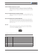
TABLE 2.
Pin
Signals
DescriptionBMS1040 BMS1060
1 TC1P TC1P Thermistor 1 terminals
4 TC1N TC1N
2 TC2P TC2P Thermistor 2 terminals
5 TC2N TC2N
3 NC TC33P Thermistor 3 terminals
6 NC TC3N
Cell Connections
In order for the system to successfully measure, monitor and balance each individual cell
in the battery pack, the cells must be properly connected to the BMS.
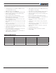
Cell Chemistry and Voltages
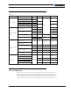
Table 3, below, shows the expected output voltage available for the load, at different
States of Charge, for different cell arrangements and chemistry. Each of these values can
be adjusted in the BMS configuration to different operating/charge conditions.
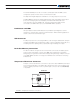
TABLE 3.
Cells
LiPo LiFe
Minimum Nominal Maximum Minimum Nominal Maximum
Empty 80%-20% SoC Full Charge Empty 80%-20% SoC Full Charge
6 18 22.2 25.2 15 19.8 21.6
BMS1040
7 21 25.9 29.4 1 7. 5 23.1 25.2
8 24 29.6 33.6 20 26.4 28.8
9 27 33.3 37.8 22.5 29.7 32.4
10 30 37 42 25 33 36
11 33 40.7 46.2 27.5 36.3 39.6
BMS1060
12 36 44.4 50.4 30 39.6 43.2
13 39 48.1 54.6 32.5 42.9 46.8
14 42 51.8 58.8 35 46.2 50.4
15 45 55.5 63 37.5 49.5 54
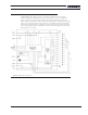
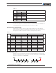
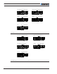
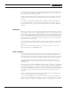
Connecting the cells
A 16-pin connector is used for the necessary monitoring and balancing connections. The
drawings in Figures 6-8, below, show how to connect 6 to 10 cell packs on the BMS1040,
and 11 to 15 cells packs on the BMS 1060.
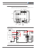
Pack+Pack-
B0 B1 B2 B3 B4 B13 B14 B15
- - - - -
.
FIGURE 6. Battery Cell Configuration