OpenTracker 2.4 User Manual Release 1.4.
www.geolink.io Table of Contents Introduction ...................................................................................................................................................... 4 Hardware Description...................................................................................................................................... 5 Board Overview ............................................................................................................................................
www.geolink.io Connector schematic (2G modem only) .................................................................................................. 21 Optional connector (3G modem only) ...................................................................................................... 21 USB Interface ................................................................................................................................................. 22 JTAG Interface ........................................
www.geolink.io Introduction The OpenTracker v2 is the first 100% Arduino compatible, fully open source, commercial grade GPS/GLONASS vehicle tracker development board that comes with a free web interface for tracking. The OpenTracker v2 hardware includes the same powerful 32-bit ARM controller as the Arduino DUE, a GSM/GPRS modem for wireless connectivity, a GPS/GLONASS module with Assisted-GPS, CAN-BUS, plenty of I/O, and a wide operating temperature range of -35°C to +80°C.
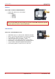
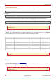
www.geolink.io Hardware Description Board Overview Internal Expansion Pins USB Programming Connector Audio Interface Quectel M95 GSM/GPRS Modem GSM Antenna Connector Indicator LEDs microSIM Slot Main Connector GPS Antenna Connector ATMEL Processor JTAG Quectel L76 GPS/GLONASS Module OpenTracker is an open-source development platform for vehicle tracking applications, compatible with Arduino software and development environment.
www.geolink.io Modem Quectel M95 - Quadband GSM/GPRS Modem GPRS data uplink transfer: max 85,6kbps Quad-band: o GSM850 o GSM900 o DCS1800 o PCS1900 Take note of the IMEI code on the modem (you can also scan the QR code) because you will need it to register your device on the Geolink website.
www.geolink.io Quick Start Guide Install Arduino IDE The Arduino IDE is an integrated development environment used for OpenTracker. If you plan to modify the program code or write your own there is no way around it. Please note: The tracker comes pre-programmed, if you only want to get started tracking just skip this step. OpenTracker requires Arduino IDE 1.6.7 or later. The download should be just below 100MB while downloading the installer and the installation process you may move on the next steps.
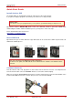
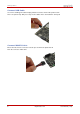
www.geolink.io Connect USB Cable Use a micro USB Type B cable and plug it into the board as shown in the picture below. This is an optional step. Only necessary if new software has to be installed or developed. Connect MOLEX Cable Ensure the Latch on the connector is faced up as shown in the picture below. Push the connector until it clicks. 8 OpenTracker 2.4 User Manual (1.4.
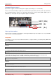
www.geolink.io Connect Power source OpenTracker supports 12V/24V nominal power supplies (the full range is 8 – 32 Volts DC). Please connect first the battery negative (B–) terminal to pin 6 (black wire), then the positive (B+) terminal to pin 1 (red wire) through a 2A fuse, as in the picture below.
www.geolink.io Change SMS password Optionally, change SMS password by sending following SMS command: #pass,smspass=NEW_PASSWORD Example: #pass,smspass=mynewpass After changing the SMS password, the SMS commands should begin with your new password, like: #mynewpass,COMMAND=ARGUMENTS Please note, depending on the current status of the device, it may take a while until the SMS response is sent. SMS Commands Summary of the SMS commands for the initial configuration.
www.geolink.io External I/O Main Connector The main connector for external power and I/O is compatible with Molex p/n 0430451006 (Micro-Fit 3.0™) Fully isolated contacts Full polarization Positive locks 3.0mm (.118") Pitch Current rating: 5.0A (per circuit) Voltage rating: 250V AC,DC UL 94V-0 Pin assignment CAN BUS Interface OpenTracker features a standard CAN Bus interface on the main connector.
www.geolink.io Digital Outputs Parameter Min. Relay Output Current Relay Output Voltage1 0 Typ. Max. Unit 0.2 0.5 A - 36 V Notes: 1. Relay driving outputs OUT1 and OUT2 are open-drain outputs suitable for relay coils, which should be powered externally from the same voltage as the whole device. They are protected against voltage transients and short-circuits. Hardware versions earlier than “rev2.
www.geolink.io Hands on recommendation for Relay usage Only use car relays and certified cables inside vehicles! A relay socket will ensure proper connection! Don´t do it yourself if you are unsure what you are doing. Ask a car mechanic to do this connections for you instead. Please note: It is not our responsibility to ensure you connect the relay the appropriate way. Always ensure you read the specifications of the relay you intend to use and the devices you want to operate.
www.geolink.io Analog Inputs The two inputs on the Main Connector (IN1 and IN2) are analog inputs and are able to measure voltages up to 32 volts. Parameter Analog Input Voltage2 (Normal Range) Analog Input Voltage2 (Reduced Range) Analog Input Accuracy Min. Typ. Max. Unit 0 - 36 V 0 - 3.3 V Analog Input Impedance 200 230 260 kΩ Analog Input Bandwidth 7 - 79 Hz ±0.15 V Notes: 2.
www.geolink.io Using the Inputs (IN1 / IN2) This example shows how to read the analog inputs on the Main Connector (External IO) and print the output to the debug port. 1. 2. 3. 4. 5. 6. 7. 8. 9. 10. 11. 12. 13. 14. 15. 16. 17. 18. 19. 20. 21. 22. 23. 24. 25. 26. 27. 28. 29. 30. 31. 32. 33. 34. 35. 36. 37. 38. 39. 40. 41. 42. 43. 44. 45. 46. 47. 48. 49. 50. 51.
www.geolink.io Voltage detection VDET (ignition detection) The voltage detection is designed to give feedback about the ignition status. If the Pin VDET is connected to the Ignition line of a car the Tracker is able to detect a logical 1 (Ignition off) or a logical 0 (ignition on) on S_DETECT. This is useful to put the tracker asleep or wake it up. VDET is a Digital input. Operating conditions V input VDET Logic 1 (ignition off) VDET Logic 0 (ignition on) MIN MAX MIN MAX 0VDC 0.6VDC 1.
www.geolink.io Battery monitoring (AIN_S_INLEVEL) OpenTracker can monitor the power supply voltage. This is done via the power input (VIN) and no additional cables have to be connected to the tracker. Using Battery Monitoring The following example shows how to measure the Supply voltage and print it to the debug port. 1. 2. 3. 4. 5. 6. 7. 8. 9. 10. 11. 12. 13. 14. 15. 16. 17. 18. 19. 20. 21. 22. 23. 24. 25. 26. 27. 28. 29. 30. 31. 32. 33. 34. 35. 36. 37.
www.geolink.io Customizable EXT PIN Using EXT PIN The EXT Pin on the main connector has no function. It is routed to the internal I/O connector. This may be used for anything the user desires. For example with a 1-wire communication or additional analog lines. Simply connect the IO_TO_EXT Pin on the Internal I/O pin header to your custom setup. Please note: When connecting any Internal I/O Pin to the IO_TO_EXT that those have 3.3V levels and are directly connected to the MCU.
www.geolink.io LEDs OpenTracker has two LEDs for status indication. The Green LED named NET indicates the network status of the M95 modem and cannot be used for other purpose as connected directly to the GSM Modem. The Red LED can be programmed to indicate various information. Using the LEDs PWR LED (red) The power LED can be programmed. Please see below the Arduino Example: 1. 2. 3. 4. 5. 6. 7. 8. 9. 10. 11. 12. 13. 14. 15. 16. 17. 18. #include
www.geolink.io Internal I/O The internal I/O Expansion connector is a 20-pin standard 2.54mm pitch female header. It features the following interfaces and signals: 1 x SPI 2 x UART/USART 1 x I2C 2 x Analog Input (ADC) 2 x PWM (1 shared with UART TX) GPIO (shared with any other peripherals) RESET (open-drain input/output from main controller) ERASE (full chip erase request) 3.3V 4V (exact voltage may vary around 4.
www.geolink.io Audio Interface Since board revision 2.4 the OpenTracker has internal connections for the modem audio interface, enabling voice call features. The 2G modem has analog audio support, with direct connection to an electrect condenser microphone for input and to an 8 Ohm speaker for output (max 500mW) in a “handsfree” configuration. Board variant with 3G modem has an optional digital audio interface for connection to an external PCM audio codec.
www.geolink.io USB Interface The USB connector is used to program and debug the OpenTracker board. To be able to communicate with the tracker via USB the tracker needs to be connected to a power supply as well. 1. Install Arduino IDE 1.6.7 or later on the workstation used. 2. Use a micro USB Type B cable and plug it into the board. 3.
www.geolink.io JTAG Interface OpenTracker has got a JTAG interface which may be used for programming and debugging. The JTAG connector is a not populated 10-pin .050 inch pitch male header. The recommended Debugger is the Atmel SAM-ICE for Atmel SAMA5, SAM3, SAM4, SAM7 and SAM9 ARM® core-based microcontrollers in connection with ARM-JTAG-20-10 connector Adapter from Olimex. More info at: Atmel SAM-ICE http://www.atmel.com/tools/atmelsam-ice.aspx?tab=overview ARM-JTAG-20-10 https://www.olimex.
www.geolink.io Software Arduino IDE If you just want to use OpenTracker to Track your device you do not need to do these steps. It is all there and configured for this use. But if you want to take advantage of all IO and additional features follow the instructions below and you are ready to develop your own software with Arduino IDE. Adding OpenTracker 2 as Board to Arduino IDE Make sure you have a recent Arduino IDE (version 1.6.7 or later).
www.geolink.io Troubleshooting Reset Soft bricked board – Flash locked During development process it may happen the board will be bricked and compiler output will look like: Erase flash Write 51852 bytes to flash Flash page is locked [ ] 0% (0/203 pages) Please follow the below instructions to solve this. How to Reset a Soft bricked board You can try to force a mass erase on the MCU Flash.
www.geolink.io Electrical Characteristics Absolute Maximum Ratings Stresses exceeding the maximum ratings may permanently damage the device or affect reliability. The device may not function or be operable outside the recommended operating conditions (see below). Parameter Min. Typ. Max. Unit Power Supply Voltage (VIN) 8 - 32 V Power Supply Current 0 - 1.
www.geolink.io How to get support Please feel free to contact us with any questions, queries or suggestions. If your question is about technical support or troubleshooting for one of our products, we kindly ask you to check first our documentation for a possible solution. If you cannot find the solution you are looking for, then please write to support@geolink.io providing all possible details.