
User Guide


RS-LiDAR-16 User Manual
14
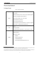
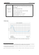
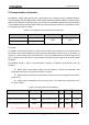
Figure 4: Aviation Plug PIN Number.
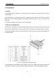
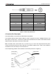
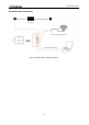
4.3 Interface Box Description
The Interface BOX is connected to the RS-LiDAR-16 by default.
The Interface BOX provides indicator LEDs for power, interfaces for power, 100Mbps Ethernet, and
GPS inputs. The DC 5.5-2.1 connector for power input, RJ45 Ethernet connector for RS-LiDAR-16 data
output and SH1.0-6P female connector for GPS input.
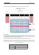
Note: The default cable of the interface box is 3 meters long, if you have other length requirements please
contact the RoboSense technical support. Because of the different LiDAR versions, there are two definitions
and different levels of the GPS port on the interface box.
The corresponding positions of the interface are as follows (As shown in Figure 5):
PIN
Wire Color
Function
1
Red
+12V
2
Yellow
+12V
3
White
GROUND
4
Black
GROUND
5
Green
GPS PULSE
6
Blue
GPS REC
7
Brown
LiDAR Ethernet RX-
8
Brown white
LiDAR Ethernet RX+
9
Orange
LiDAR Ethernet TX-
10
Orange white
LiDAR Ethernet TX+