Original Operating Instructions (EN) Robotic Mower … RC304 / RC306 / RC312 TC300 / TC500 / TC1000 MC300 / MC500 / MC1000 Operating Manual
Table of Contents Chapter 1 – Introduction and Safety………………………………………………………………… 3 1.1 Introduction…………………………………...……………………………………………… 3 1.2 Warnings Decal Definitions ……………………………………………………….…….… 4 1.3 Safety Warnings & Precautions ……………………………………………………….…. 4 1.4 Robomow Safety Features ………………………………………………………….... 6 ® Chapter 2 – Know Your Robomow ………………………………..……………...…………...…. ® 2.1 What’s in the Box.......................………………...…………….…………………………… 7 7 2.
1. Introduction And Safety EC Declaration of Conformity The products covered by this Declaration 26 Volt Battery operated Robotic Lawn Mower model: Robomow RC 304/306/312 MC 300/500/1000 and TC 300/500/1000 (with Base Station) EN Manufacturer: F. Robotics Acquisitions Ltd. Hatzabar St., Industrial Zone P.O.Box 1412 Pardesiya, 42815 Israel F. Robotics Acquisitions Ltd.
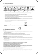
1.2 Warning Decal Definitions These are the symbols on Robomow®; Read them carefully before operating Robomow ®. 1 2 3 4 5 6 7 1. This is a dangerous power tool. Use care when operating and follow all safety instructions and warnings. 2. Read through the Operating & Safety Manual carefully before operating your Robomow®. 3. Hazard of throwing or flying objects while in operation. 4. Keep a safe distance from Robomow ® when operating.
EN Transportation – To safely move from or within the working area: 1. Press the STOP button to stop Robomow®. 2. Use the Remote Control (available as an accessory) to drive it from place to place. 3. In case of different height level, switch off the Safety Switch, and carry the mower by the carrying handle. 4. In case of long transportation, use the original packaging. 5. When transporting Robomow® over long distances switch off the Safety Switch.
1.4 Robomow Safety Features 1. Child Lock The Child Lock prevents unintended operation of Robomow® by an accidental press of one of the buttons. Only pressing of two buttons in a certain order will initiate the operation. 2. Anti-Theft / Disabling Device The Anti-Theft/Disabling Device system provides the user a disabling function that will prevent anyone from using or driving the Robomow® unless they have the valid code to enter.
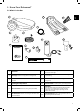
2. Know Your Robomow® 2.1 What’s in the Box 8 9 EN 1 10 2 3 12 11 4 5 6 Operating & Safety Manual 7 1 Robomow® 7 RoboRuler Used for setting the distance of the Perimeter Wire from the lawn edge. 2 Wire Pegs Used for securing the wire to the ground. 8 Base Station Used by Robomow to dock and charge when it is not mowing.
2.2 How Robomow Works for You • First, you need to install a perimeter wire around the entire lawn and around protected areas within the lawn area. • The Perimeter Wire sets the boundaries for Robomow. The Perimeter Wire is laid around the edges of the lawn and around trees, plants, ponds and objects that you want to prevent Robomow to run into. • If the supplied wire is not sufficient, more wire can be purchased and spliced with a supplied connector to the existing wire.
2.3 Operation Method • Robomow is a robotic lawnmower designed to mow and maintain your lawn completely by itself. • Simple One-Time Setup – Robomow requires a simple one time setup, which can easily be done by the consumer. Robomow recognizes the wire using special sensors, and makes sure it always stays inside the designated area. Essential accessories are supplied with the product. 3G EN • Working Method – - Robomow will automatically mow the lawn.
3. Planning Ahead Getting your lawn ready for Robomow is rather simple. Still, as every lawn is unique, we recommend reading this chapter before starting to install the perimeter wire. Planning the wire route and drawing a sketch of the lawn, including all obstacles and Base Station location, will make it easier and will prevent mistakes during the setup. Watch Robomow setup & operation video. Also available on Robomow website.
3.1.2 “Main Zone + Sub-Zone(s)“ Type Lawn Su b-Z on e EN This type of lawn consists of more than one zone and these zones are connected by a narrow pass. In this type of lawn, Robomow will be able to drive from one zone to the other in order to mow the whole area.
Types of Separated Zone setups: A Separated Zone smaller than 100 m² (1100 ft²) o Separated area that is smaller than 100m² (1100 ft²) can be covered in a single operation, thus, if possible, the separated area may be connected to the main area’s Perimeter Wire (have the signal come from the Main Base Station). Separated Zone Smaller than 100m² (1100ft²) 2 Wires under same peg Or o It may need its own separate Perimeter Wire.
There are two options to set the Base Station: 3.2.2 Internal Setup (on the lawn perimeter) EN Choose a place along the Perimeter Wire where you want to place the Base Station, based on the inputs given in paragraph 3.2.1. Place the Base Station in the direction shown in the figure to the right. 3.2.3 External Setup (off the lawn perimeter): There are two types of External Setup: A.
3.3 Select Power Box Location Consider the following in order to select the Power Box location: The Power Box will be connected to the Base Station using the 15m (50ft.) Extension Cable. Select a suitable location for the Power Box to be mounted on a wall near a power outlet. Locate it outside the lawn perimeter. Select an easily accessed spot. Select a dry and sheltered location. The Power Box is to be mounted vertically. The Power Box is suitable for Outdoor use.
Slope inside the lawn Robomow can mow areas inside the working area with a slope of up to 35% (35cm rise per 1m). Tip: If the mower tilts off the ground while climbing a slope, it is too steep. Exclude this steep area from Robomow’s cutting area. EN In Lawn Slope 35% How to calculate the slope of your lawn? Length 35cm (1.1ft) Max 35% slope Elevation 100cm (3.3ft) How to calculate the slope of your lawn? 35cm (Elevation) 100cm (Length) 35% (slope) 3.4.
4. Initial Setup 4.1 Preparations Recommendations before you start: During setup, you will insert pegs into the ground. To complete this task smoothly, we recommend not to do it while the grass is high and to water it before starting. Hammer Combination Piers 4.1.1 Getting Ready Make sure all parts needed for setup are within reach. Have the Robomow box nearby, so all items are available.
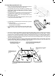
4.2.1 Starting Point: Perimeter Wire at the Base Station area. Do not place the Base Station within 3m (10 ft.) of a corner EN • ft) 0 er (1 rn m co . 3 ny in a M om fr • Place the Base Station, according to your plan, as shown in the figure to the right. • Select the roll of wire with a green plot connector attached to the end. • Pull the plot connector and some wire out of the plastic covering. ! Do not remove the spool of wire from its covering. The plastic covering is the dispenser for the wire.
• If the working area borders against a flat path that lies level with the lawn, it is possible to allow Robomow to run over the path. The Perimeter Wire should then be laid 10 cm (4 inches) from the edge of the path. • When the working area is divided by a flat path that is level with the lawn, it is possible to allow Robomow to run over the path. The Perimeter Wire can be laid under the pavement blocks or in the joint between them.
4.3 Perimeter Wire within the Working Area 4.3.1 Hard Obstacles o Obstacles that can withstand a collision, for example, trees or bushes higher than 15 cm (6”), do not need to be demarcated by the Perimeter Wire. Robomow will turn when it collides with this type of obstacle. EN 4.3.2 Perimeter Islands o o o o o o o Use the Perimeter Wire to demarcate areas inside the working area by creating islands around obstacles that cannot withstand a collision, for example, flower beds and fountains.
4.3.3 Setting a Narrow Pass A Narrow Pass is defined as a path that connects two zones of the lawn. The path enables Robomow to drive between the zones while following the wire, but prevents the mower from crossing between them while mowing the inner area of the zones. To set up a Narrow Pass follows the instructions given in the figure below: Sub-Zone A. At the point you want the mower to start driving towards the Sub-Zone start to set the Narrow Pass. Perimeter Island 30x30 cm B.
If the Narrow Pass is wider than 2m (6.5ft.), and you want Robomow to mow the area inside the Narrow Pass, then you can set the wire as shown in the figure below. Such a setup allows the mower to mow inside the Narrow Pass while mowing the inner part of the lawn, but prevents it from crossing between the zones. A. At the point you want the mower to start driving towards the SubZone start to set the Narrow Pass. B.
Use only the wire connectors supplied with Robomow. Neither Twisted cables, nor a screw terminal insulated with insulation tape are a satisfactory splice. Soil moisture will cause the conductors to oxidize, which will later cause a broken circuit. 4.5 Back at the Base Station – Completing the Perimeter Wire Setup Once the Perimeter Wire loop is completed and pegged to the ground, complete the setup by attaching the beginning and the end of the Perimeter Wire to the Base Station Head.
o After the Base Station has been positioned, insert 2 stakes into the Base Station holes as shown in the figure to the right. Only after the Base Station position has been tested during the One-Time Setup process (see Section 5.2), you will be able to insert the remaining two stakes. EN 4.7 Connecting the Power Box In order to find a proper location for the Power Box, please refer to Section 3.3. For the Power Box installation instructions please refer to Section 4.1.2.
4.8 Setup in a Non-Base Zone A Non-Base Zone is an area of the lawn that is not connected to a Base Station. A Perimeter Switch should be installed in these areas. When necessary, the Perimeter Switch can be easily moved to other zones. The Perimeter Switch MUST be Mounted vertically in order to maintain its’ water resistance 4.8.
• Lay the Perimeter Wire from the Perimeter Switch to the lawn. 2 wires under the same peg • Start laying the wire in anticlockwise direction. EN • Once completing the Perimeter Wire loop, lay the wire back towards the Perimeter Switch. • At the end of the Perimeter Wire loop, you have now two wires. Lay the two loose wires in the direction of the Perimeter Switch location and peg them to the ground using a single peg for both. 4.8.
2 • Hold the Perimeter Switch and squeeze its side tabs (1) to remove it from the back cover (2). • Connect the Power Supply plug to the Perimeter Switch board. Replace the cover. • Connect the power supply to a regular power outlet (230V / 120V). 1 ! IMPORTANT ! The Power Supply is for indoor use ONLY. Choose a sheltered, dry, and well ventilated location that is NOT exposed to direct sunlight, water, or rain. • Press the ‘ON’ button on the Perimeter Switch.
5. Preparing Robomow Before using Robomow for the first time, you have to perform some simple preliminary settings. Once the preparations are complete, your Robomow will be ready to mow your lawn. EN 5.1 Adjust the Cutting Height Safety Switch Blade Cutting Range: 15 – 60 mm (0.6 – 2.4 inches) To adjust the cutting height of the blade, do the following: CAUTION! ALWAYS TURN THE SAFETY SWITCH OFF BEFORE ADJUSTING THE CUTTING HEIGHT! • • • • • Lift the front side of the mower.
5.2.4 Main Zone Area • Scroll to select an approximate area (EU- m² / US- ft²) for the Main Zone, where the Base Station is installed. If an additional zone (Sub-Zone or Separated Zone) exists, do not include it in main zone’s area (it will be set separately). Note – It is necessary to complete the above settings (5.2.1 – 5.2.3) in order to operate the mower. Every press on the STOP button will change the screen one step back in the process. 5.2.
5.2.6 Test Wire Position • U003 is displayed (Test Wire Position) – press OK. • Robomow will follow the wire along the edge to test the wire position. EN Walk alongside Robomow while it is following the edge. Having completed the process, Robomow will enter the Base Station and the setup process will be completed. If the mower collides with obstacles along the edge, the mower will stop and drive backwards with ‘U052’ (Adjust Wire) displayed: • Move the wire slightly inward.
6. Robomow Operation 6.1 Automatic Operation o As a part of the One-Time Setup, you have defined the area of your lawn. Based on this setting, Robomow will automatically derive the required number of mowing hours for your lawn (Mowing Cycle). o Once the One-Time Setup is finished, Robomow will be set to perform automatically the following cycle of mowing operations: - When the battery is fully charged, Robomow will automatically depart from the Base Station. - It will mow the lawn.
OK to choose / approve selection Settings ok STOP Mowing without Edge / Right arrow EN Mowing with Edge / Left arrow GO to Base (Home) Stop (during operation) / Back while in the menu 6.3 Manual Operation Manual Operation is used when you want to manually send the mower to mow your lawn, regardless the Automatic Operation’s schedule. To initiate Manual Operation, while Robomow is at the Base Station, press one of the buttons (except the STOP button) to show the display.
6.4 Menu Options There are several levels of menu options that can be set in your Robomow: A. Basic Settings B. Advanced Settings C. Robomow App Settings 6.4.1 Basic Settings The Basic Settings are the most common menu options changed by the user. Each of the Basic Settings has an icon on the mower (refer to 6.2 – Operating Panel) that is lit to indicate the selected menu option. o To change Basic Settings, press the ‘Settings’ button.
6.4.1.4 Area – Update the size of the lawn in case it has been changed. EN • Press the ‘Setting’ button 4 times until the Area icon is blinking. • Scroll to change the area and press ‘OK’ to confirm. • If more than one zone is defined, then first scroll to select the zone you want to edit and set the area for that zone as described above. Names of zones are as follows: L1 – Main Zone L2 – Separated Zone A L3 – Separated Zone B A1 – Sub-Zone 1 A2 – Sub-Zone 2 A3 – Sub-Zone 3 A4 – Sub-Zone 4 6.4.
Screen Setting • When Robomow completes its operation, or when the ‘Home’ button instructs it to Go To Base, it drives itself to the Base Station. • Robomow drives along the Perimeter Wire with a dynamic offset (not centered) to prevent wheel tracks along the same path. This return behavior can be turned off. Options P003 Near Wire Follow (Default = ON) P004 • The maximum distance Robomow will drive from wire when returning to the Base Station.
Screen Setting P012 Anti-Theft / Disabling Device Description Options 0000 P013 Base Station (Default = ON) • This option should be used in a Separated Zone which has a Base Station • If you have defined more than one zone, then select the relevant zone before changing the setting. On/OFF P014 Add Separated Zone • Enables the addition of a Separated Zone. • L2 is displayed for Separated Zone A – press OK. • Scroll to set the area of the Separated Zone and press OK.
Screen P024 Setting SmartMow (Default = OFF) SmartMow P025 Edge Overlap (Default = 10) P026 TurboMow (Default = OFF) Description Options • Enables the unique SmartMow feature. • SmartMow feature allows more efficient mowing operation through the smooth and continuous turns when reaching lawn’s edge. • This feature may not be efficient in the same way in every lawn or in some parts of a particular lawn.
7. Using The Power Box 7.1 Power Box Alerts Event Description The mower is in its Base Station. Operating Indicator is lit The mower is not in its Base Station. Program On/Off Indicator is lit. ‘OFF’ will be displayed on the mower. On/Off Button EN Docking Indicator is lit. Docking Indicator Automatic Operation is paused. Wire Indicator – Flashes and Beeps The Perimeter Wire is cut, disconnected, or too long.
8. Charging 8.1 Charging During the Season The Base Station is the primary charging source when Robomow is docked and will maintain the optimal battery charge while awaiting departure. 8.2 Charging Out of Season During out of season months, such as winter, it is required to: • Fully charge the battery in the Base Station till the Battery indicator is green and lit constantly. Note! The Safety Switch should be in ‘On’ position during charging.
The following table displays all Error Codes and gives possible causes and corrective actions: Display E2 Stuck in Place The mower is Outside Probable Cause/Event Corrective Actions -- Remove the mower away from this particular location and restart operation. -- Rectify the reason for it getting stuck. -- Robomow got stuck in place. It cannot continue driving. -- Drive wheel motors have been working under a severe load.
Display E 6 Message Check Drive Probable Cause/Event -- Grass or other object has wrapped around the drive wheel. -- The drive motors have been working under severe load for too long. Corrective Actions -- Check the drive wheels and remove the grass or other objects. -- If Robomow has driven onto an obstacle, Switch off the Safety Switch, raising the front end: Remove or exclude the object from the mowing area.
Display 0016 Message Low temperature Probable Cause/Event --Mower does not depart automatically from the Base Station when the ambiance temperature is lower than 5ºC (41ºF). --No need to do anything. --Robomow will renew the operation automatically as soon as the ambiance temperature will rise above 5ºC (41ºF). EN --Information – When the temperature is below 5ºC (41ºF) the grass does not grow or grows very slowly. Corrective Actions However Manual Depart is enabled.
9.3 User Messages The next table gives information about User Messages that can be displayed on the mower: Display Message / Description BATT Recharge Battery. Low battery voltage. Recharge the Battery. U001 Test Base Station position. Displayed during the One-Time Setup. Refer to section 5.2.4 in the User Manual. U002 Peg Base Station. Displayed during the One-Time Setup. Refer to section 5.2.4 in the User Manual. U003 Test wire position. Displayed during the One-Time Setup.
Display Message / Description Sub-Zone 1/2/3/4 entry problem. The mower eitherfails to leave/bypassthe Base Station on its way to the Sub-Zone,orfails to enter the Sub-Zone. U094 The mower will try to reach the Sub-Zone every two hours. If the mower fails to reach the SubZone within threeattempts, it will stay in the Base Station until the end of current mowing cycle. Try to startmanual mowing (refer to section 6.3 – Manual Operation).
Problem Encountered Probable Cause/Event Uneven mowing results -- The time between operations is too long because of long inactive time windows. -- Minimize the Inactive Time windows to allow Robomow to complete the Mowing Cycle faster and to achieve even mowing results. -- Grass is growing very fast. -- -If it is during a fast growing season – change the Mowing Frequency (refer to Section 6.4.2 – P001). -- In a complicated lawn more time is required for the lawn to achieve better mowing results.
Code Description Corrective Action One-Time setup should be completed before the automatic operation can start 11 Automatic operation is disabled by menu P021 (see Section 6.4.2) Enable automatic operation through menu p021 12 Automatic operation is put on pause bythe Power Box Un-pause automatic operation on the Power Box or through menu P021 13 All week days are set as inactive days Validate Inactive Time settings (see Section 6.4.
10. Product Specification RC 304 RC 306 RC 312 Designation Robotic Mower Robotic Mower Robotic Mower Max Lawn Size 400 m² / 4400 ft² 600 m²/ 6600 ft² 1200 m²/ 13000 ft² Base Station Included Included Included Robot Dimensions 63x46x21cm/25x18x8” 63x46x21cm/25x18x8” 63x46x21cm/25x18x8” Package Dimensions 80x54x33cm/32x21x13” 80x54x33cm/32x21x13” 80x54x33cm/32x21x13” Robot Weight 11.1 kg / 24.5 lb. 11.1 kg / 24.5 lb. 11.1 kg / 24.5 lb. Package Weight 22.8 kg/ 50.5 lb. 22.
11. Maintenance and Storage 11.1 General Instructions • • • EN • Always switch off the Safety Switch of Robomow® before checking/ cleaning/ working on Robomow® or replacing the blade. Never attempt to service or adjust the mower while it is in operation. Check and clean Robomow® regularly and replace worn parts to improve performance and operation and to ensure a longer lifetime of your product.
• • Inspect the underside of the mower periodically. Clean if necessary. Carefully scrape the collected grass debris from under the mowing deck. -- Most grass accumulation can be removed using a small wooden stick or similar object. -- You may remove the blade to gain better access to the mowing chambers. IMPORTANT! Do not place the mower upside down. Instead, lean the mower against a surface to gain access to the mowing deck area.
11.6 Splicing the Perimeter Wire If the Perimeter Wire needs to be spliced, use the connectors supplied in the Robomow box. It is waterproof and gives a reliable electrical connection. EN IMPORTANT! Before slicing the Perimeter Wire, disconnect the PowerBox from the power outlet. 1. Strip 1 cm (0.5 inch) of each wire end together and twist the stripped ends using pliers. 2. Insert the twisted wires into the splicing connector. 3. Screw the wire connector on the twisted wires.
12. Accessories Blade (Part No. MRK7003A) Keep a spare blade on hand. A sharp blade is important for safety and best cutting performance. Used to replace the existing battery and refresh cutting capacity. Peg Pack Perimeter Wire (Part No. MRK0012A) (Part No. MRK0014A) Used to fasten the Perimeter Wire to the ground. For larger lawns or additional zones. For larger lawns or additional zones. Wire Repair Connectors (Part No. MRK0039A) Used for repairing or splicing wires.
13. Tips for maintaining your lawn Robomow® – Lawn care has never been so easy EN Best time to mow Mow your lawn when the grass is dry. This prevents the clippings from clumping and leaving piles on the lawn. Mow it late in the day rather than during the heat of the day. Mowing frequency Mow often in order to produce short, small clippings. During the active growing season the mowing frequency should be increased to once every 3-5 days, before the grass is too long.
Warranty Card ‘C’ Series Limited Warranty Friendly Robotics warrants to the original purchaser that the ‘C’ series ‘Product’ is free from defects in materials and workmanship when used under normal residential* purposes for a period of three years** (on RC models purchased in Europe), two years (on TC/MC models purchased in Europe) or one year (on any models purchased in the US), one year on the batteries, beginning from the date of purchase.