
User's Manual


© 2004 SPX Corporation
44
44
4
Introduction
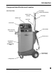
Component Identification and Location
continued
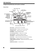
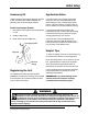
Control Panel
New Fluid In — Displays amount of fluid added.
Replaced Fluid Out — Displays amount of fluid extracted.
UP/DOWN Arrows — Adjusts amount of fluid in or out.
Pause/Abort — Pauses or aborts a transfer.
Error Message Indicators — Displays error message.
Mode Indicators — Identifies procedures available.
Select Button — Selects the desired mode or procedure.
Enter Button — Accepts mode selected and starts the ATF exchange.
Display Screens — Displays operational or error information.
Transfer Indicators and LEDs — Indicates the transfer that is presently
taking place.
ON/OFF Power Switch — Turns the unit on.
N
e
w
F
l
u
i
d
i
n
.
.
.
.
.
.
R
e
p
l
a
c
e
d
F
l
u
i
d
o
u
t
DIPSTICK ONLY
DIPSTICK/COOLER
COOLER ONLY
MANUAL/TOP-OFF
DRAIN WASTE TANK
TOTAL COUNT
SUPPLY
LINE
RETURN
LINE
REVERSED
POLARITY
SELECT
ENTER
FINISH
CHECK
END
SERVICE
SERVICE
START
START
ENGINE
LEVEL
T
r
a
n
s
m
i
s
s
i
o
n
F
l
u
i
d
E
x
c
h
a
n
g
e
r
ON/OFF Indicator Light
Arrow Buttons:
Down
Up
Pause/Abort
Button
Light Indicators:
Reversed Polarity
Supply Line
Return Line
Select Button
Finish LED
Check Trans Level LED
End Service LED
ON/OFF
Switch
Mode LED Indicators:
Dipstick Only
Dipstick/Cooler
Cooler Only
Manual/Top-Off
Drain Waste Tank
Total Count
Enter Button
Start Service LED
Start Engine LED
Transfer Indicators: ATF In ATF Out
I
O
Transfer LEDs:
To Trans From Trans