® OPERATING MANUAL ○ ○ ○ ○ ○ ○ ○ ○ ○ ○ ○ ○ ○ ○ ○ ○ ○ ○ ○ ○ ○ ○ ○ ○ ○ ○ ○ ○ ○ ○ ○ ○ ○ ○ ○ ○ ○ ○ ○ ○ ○ ○ ○ ○ ○ ○ ○ ○ ○ ○ ○ ○ ○ ○ ○ ○ ○ ○ ○ ○ ○ ○ ○ ○ ○ ○ ○ ○ ○ ○ ○ ○ ○ ○ ○ ○ ○ Model 92500 Transmission Fluid Exchanger
® Transmission Fluid Exchanger Unit Model: 92500 SAFETY DEFINITIONS: Follow all WARNING, CAUTION, IMPORTANT, and NOTE messages in this manual. These messages are defined as follows: WARNING means you may risk serious personal injury or death; CAUTION means you may risk personal injury and property damage or serious unit damage; IMPORTANT means you may risk unit damage; and NOTEs provide clarity and helpful tips. These safety messages cover situations ROBINAIR is aware of.
Table of Contents Safety Warnings ........................................................... inside front cover Introduction ......................................................................................... 2 General Description ......................................................................................... 2 Glossary of Terms ............................................................................................ 2 Component Identification and Location ..............................
Introduction General Description The 92500 provides an easy, efficient way of replacing automatic transmission fluid in a vehicle. The Exchanger removes the used transmission fluid and replaces it with new fluid, which reduces the harmful contaminants and restores the fluid properties, extending the life of the vehicle’s transmission. Glossary of Terms ATF — Automatic transmission fluid (oil). Unit — The transmission fluid exchanger.
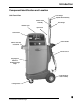
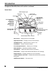
Introduction Component Identification and Location Hose Hanger Unit Front View Dipstick Wand Assembly Selector Valve Assembly Hose Hanger Indicator Light Nylon Hose Control Panel Shelf for tools and accessories Built-in Handle Tank for new oil Polypropylene Cabinet for durability and light weight Large Wheels for ease of mobility Locking Casters Transmission Fluid Exchanger 3
Introduction Component Identification and Location continued Control Panel ON/OFF Indicator Light Transfer LEDs: To Trans From Trans Pause/Abort Button Arrow Buttons: Down Up Mode LED Indicators: Dipstick Only Dipstick/Cooler Cooler Only Manual/Top-Off Drain Waste Tank Total Count Light Indicators: Reversed Polarity Supply Line Return Line ... R eplaced luid out N e w Fluid in...
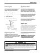
Initial Setup Accessory Kit Application Notes Unpack Accessory Kit located inside the rear door of unit. Accessory Kit includes: Adapter set, warranty card, and hose hanger bracket. Ford Taurus with a 3.0 liter V6 requires the removal of the vent cap located behind the shifter linkage on top of transmission before service. This will minimize “overfilling” due to lack of headroom in the transmission housing. Attach Hose Hanger Bracket 1. Drop tube all the way down over existing tube on unit. 2.
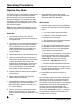
Operating Procedures Dipstick Only Mode The Dipstick Only mode transfers used ATF and new ATF through the transmission’s dipstick tube by running a hose into the transmission fluid pan, emptying it of its contents, and then with engine running, adding ATF. ATF is then subtracted until a user specified amount of new ATF has been added. Note: Confirm vehicle and transmission are at operating temperature before initiating service. Power Up 1.
Operating Procedures Dipstick Only Mode continued When the selection in step 8 is met, the buzzer sounds and the End Service and ENTER LEDs light. 4. Press ENTER to confirm that the correct amount of ATF has been replaced. Check Trans Level LED lights. Check the ATF Level in the Pan 1. Remove the flexible nylon hose. 2. Insert the dipstick. 3. Remove dipstick to check level of fluid. If the fluid level needs to be adjusted, continue on to “Adjust the ATF Level.
Operating Procedures Dipstick/Cooler Mode Initially transfers used ATF and new ATF through the transmission’s dipstick tube. Then with the engine running, new ATF is pumped into the transmission through the dipstick tube, while the old ATF is evacuated through the cooler lines. This mode provides the quickest transfer of used and new ATF. Note: Confirm vehicle and transmission are at operating temperature before initiating service. Identify Cooler Lines 1.
Operating Procedures Dipstick/Cooler Mode continued e. The volume of new fluid yet to be pumped into the transmission pan is shown on New Fluid In display (the amount designated in “Power Up” step 10 minus the amount transferred in “Start Service” step 1d). f. The Start Engine and ENTER LEDs flash. 2. Start the vehicle’s engine to circulate the ATF through the transmission system (torque converter and cooler lines). Adjust the ATF Level 1. Place the flexible nylon hose in the dipstick tube.
Operating Procedures Cooler Only Mode Transfers used ATF and new ATF through the cooler lines. Note: Confirm vehicle and transmission are at operating temperature before initiating service. Identify Cooler Lines 1. Disconnect cooler lines, and attach adapters to the input and output connectors. Power Up 1. Connect the power cord to a 12V DC battery: red to the positive post and black to the negative post. 8. Press ENTER to confirm the selection.
Operating Procedures Cooler Only Mode continued Manual/Top-Off Mode Check the ATF Level in the Pan Transfers used ATF and new ATF through the transmission’s dipstick tube. This mode is commonly used when the transmission fluid pan needs to be removed (to change gaskets or replace a filter). When using another mode, this mode is required to top off the ATF fluid level. 1. Remove the dipstick to check level of fluid in transmission fluid pan.
Operating Procedures Manual/Top-Off Mode continued 2. Press ENTER. The amount removed will display on the Replaced Fluid Out display. Adjust the ATF Level 3. Adjust the New Fluid In display to match the Replaced Fluid Out display. 1. In step 2 under “Power Up,” the ATF level was determined noting whether ATF needed to be added, subtracted, or it was satisfactory. 4. Press ENTER. a. If the level is too low, select To Trans LED. (1) Press Enter.
Operating Procedures Total Count Displays the number of ATF exchanges performed. Power Up 1. Connect the power cord to a 12V DC battery: red to the positive post and black to the negative post. 2. Turn the unit on. The Reversed Polarity LED lights if the power is connected incorrectly. The unit self-tests: The buzzer sounds, all LEDS and displays light and flash, the flexible nylon hose evacuates ATF, and the software version displays.
Error Messages ER FLO — Return Line is lit. No oil is returning. ER FLO — Supply Line is lit. Check new oil reservoir. Reversed Polarity is lit. Check battery connections. Maintenance • Check the flexible nylon hose for cuts and/or kinks. • Filter screens may need to be cleaned. Locate the filter screens inside the unit; clean if necessary. • Cabinet can be kept clean by wiping it down with a clean cloth. • Check wires for cuts and/or damage.
Replacement Adapters 529567 - Complete adapters kit. All replacement adapters described below are included in the kit. Part Order No.
Replacement Adapters contd. Part Order No. Description Application Original No.
Replacement Adapters contd. Part Order No. Description Application Original No.
Replacement Adapters contd. Part Order No. Description Application Original No. 546763 S/48 x 9" Hose - Drain Hose Assy.
Replacement Parts Illustration B Part Number Description 92501 Pump Assembly Replacement 92501RBK Pump Head 90516 New Oil Reservoir Cap Quick Disconnect Coupler, S/25 x 1/4" Internal NPT 92509 (A in illustration) 2 Required 92510 Directional Valve Assembly (Entire assembly shown at left) A 92511 Quick Disconnect Plug, S/48 x 1/4" External NPT (B in illustration) 92513 Pressure Hose (Red; 92" x 3/8" Barb Assembly) 92514 Recovery Hose (Black; 92" x 3/8" Barb Assembly) 92515 Cooler Hose (Black
Limited Warranty Robinair Limited Warranty Statement Rev. November 1, 2005 This product is warranted to be free from defects in workmanship, materials, and components for a period of one year from date of purchase. All parts and labor required to repair defective products covered under the warranty will be at no charge. The following restrictions apply: 1. The limited warranty applies to the original purchaser only. 2.
% Visit our web site at www.robinair.com or Call our Toll-Free Technical Support Line at 800-822-5561 in the continental U.S. or Canada. In all other locations, contact your local distributor. To help us serve you better, be prepared to provide the model number, serial number, and date of purchase of your unit. To validate your warranty, complete the warranty card attached to your unit, and return it within ten days from date of purchase.