Operating Manual for Model 34988 Recovery, Recycling, Recharging Unit
Model 34988 Recovery, Recycling, & Recharging Unit SAFETY DEFINITIONS: Follow all WARNING, CAUTION, and NOTE messages in this manual. These messages are defined as follows: WARNING means you may risk serious personal injury or death; CAUTION means you may risk personal injury, property damage, or unit damage; and NOTEs and OPERATING TIPS provide clarity and helpful information. These safety messages cover situations ROBINAIR is aware of.
Table of Contents Introduction Technical Specifications . . . . . . . . . . . . . . . . . . . . . . . . . . . . . . . . 2 Control Panel Functions . . . . . . . . . . . . . . . . . . . . . . . . . . . . . . . . 3 Glossary . . . . . . . . . . . . . . . . . . . . . . . . . . . . . . . . . . . . . . . . . . . . 3 Menu Functions . . . . . . . . . . . . . . . . . . . . . . . . . . . . . . . . . . . . . . . 4 Setup Unpack the Accessory Kit . . . . . . . . . . . . . . . . . . . . . . . . . . . . . . .
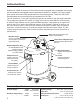
Introduction Robinair No. 34988 is used on R-134a vehicles and is designed to be compatible with existing service equipment and standard service procedures. Model No. 34988 is a UL-listed, singlepass system that meets SAE specifications for recycled refrigerant. Follow the SAE-J2211 recommended service procedure for the containment of R-134a. The unit includes a 1.5 cfm (42 l/m) Robinair high vacuum pump for fast, thorough evacuation.
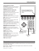
Introduction Control Panel Functions AUTOMATIC activates a menu that helps the user set up an automatic recover / vacuum / leak test / charge sequence. CHARGE activates the sequence that charges the vehicle A/C system with a programmed amount of refrigerant. EXIT returns test sequence to previous screen. HELP displays screens that explain information or steps to take. INJECT OIL injects oil into vehicle A/C system.
Introduction Menu Functions Adjust Refill Default Refrigerant Management When connected to a refrigerant source, the unit maintains a pre-set amount of refrigerant in the internal storage vessel. This value may be adjusted up or down to suit the user’s needs. (The default is 15 lbs.). Displays the amount of refrigerant recovered, charged, and replenished (for the life of the unit), and filtered (since the last filter change).
Setup Unpack the Accessory Kit Unpack the accessory kit from the box, and remove the plastic packaging. The kit consists of • A calibration weight. • Vacuum pump oil, oil filler cap, and tube. • Service hoses. • Four bottles—oil reservoir, oil drain, UV dye reservoir, spare reservoir. • Three rolls of paper for the printer.
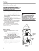
Setup UV Dye Inject Bottle 1. Unscrew the lid from the UV dye reservoir and remove the piston. 2. Fill the reservoir with UV dye only to the MAX FILL line. Overfilling the reservoir will compromise the o-ring seal and may cause air to be injected into the vehicle system. 3. Spread a thin film of oil or dye on the piston o-ring (to reduce seal drag), and thread the lid onto the reservoir. 4. Slowly push the piston into the reservoir unil you see dye at the connector. 5.
Setup Select Units The operator may choose to have units of measure displayed in pounds, kilograms, ounces, or grams. 1. Use the UP or DOWN arrow key or select TOGGLE UNITS to toggle through the choices. 2. Select SAVE to choose the displayed unit of measure. CAUTION: R-134a systems have special fittings (per SAE specifications) to avoid cross-contamination with other systems. DO NOT adapt your unit for a different refrigerant — system failure will result.
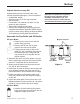
Setup Maintain Vacuum Pump contd. CAUTION: The vacuum pump is shipped without oil in the reservoir. Failure to add oil will damage the vacuum pump. 2. Remove the plug from the vacuum pump oil fill port. 3. Attach the flexible tube/cap to the oil bottle (from the accessory kit); pour only five (5) ounces of vacuum pump oil into the fill port. Note: You will top off the oil in the next step as the vacuum pump is running. 4. Select NEXT.
Setup Manual Tank Fill contd. 4. Press START to begin filling the internal storage vessel. Add at least 8 lbs. of refrigerant to ensure enough is available for charging. This process takes 15–20 minutes. The unit stops when the designated amount of refrigerant has been transferred to the internal tank, or when the source tank is empty. Note: Only the amount of refrigerant available for charging is displayed. For example, if the tank fill default is set at 15 lbs., the unit will transfer 15 lbs.
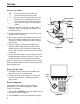
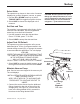
Operating Instructions Recover Refrigerant from a Vehicle 1. Empty the oil drain bottle before starting a recovery. Remove the oil drain bottle from the machine by pulling the bottle straight down from the magnetic connector — do not use a twisting or rocking motion. See Figure 6. Note: The machine gives an alert when the oil drain bottle needs to be emptied, but it is a good practice to completely empty the oil drain bottle before recovering an A/C system to prevent an inaccurate oil charge later. 2.
Operating Instructions Evacuate the A/C System 1. Ensure service hoses are connected to the vehicle A/C system, and coupler valves are OPEN. 2. Select VACUUM. 3. The unit gives you the option of doing a leak test after evacuation. Select TOGGLE LEAK to turn the leak test OFF / ON. 4. Select START to accept the default evacuation time, or enter the desired vacuum time using the number keys, and select START.
Operating Instructions Flushing the Hoses If the next vehicle to be serviced contains a different type of oil than the previous vehicle serviced, it is recommended that the service hoses be flushed of residual oil to prevent contamination. 1. Connect the service hoses to the unit’s storage port connections (shown in Figure 7). 2. Open the coupler valves by turning the collars clockwise. Storage Port Connections 3. Select HOSE FLUSH.
Operating Instructions Recharge the A/C System 1. Connect service hoses to the vehicle’s service ports. 2. Select CHARGE. The display reads CHARGE MENU CHARGE AMOUNT: 0.00 LB CHARGE MODE: ______SIDE USE ARROW KEYS TO SCROLL UNITS. 3. At this point, select INJECT OIL, if necessary. The display reads OIL XXX INJECT DYE _______ Use the number keys to enter the amount of oil to inject. 4. Select TOGGLE DYE to turn dye inject ON or OFF. Select SAVE to return to the charge screen. 5.
Operating Instructions Recharge the A/C System contd. 7. When the charge is complete, the display shows CHARGE DIAGNOSTICS HIGH SIDE XX PSI MAX XX PSI LOW SIDE XX PSI MIN XX PSI CHARGE AMOUNT: XX.XX LBS START A/C TO PERFORM DIAGNOSTICS OR WITH A/C OFF, PRESS NEXT TO CLEAR HOSES. To obtain current pressure readings and diagnostics from the vehicle, start the vehicle's air conditioning system (set at maximum output), or select NEXT to continue. 8.
Operating Instructions Recharge the A/C System contd. 9. If EQUALIZE was selected, the display reads HOSE EQUALIZE CONNECT LOW SIDE SERVICE HOSE TO A/C SYSTEM AND OPEN COUPLER. MAKE SURE HIGH SIDE HOSE IS DISCONNECTED FROM A/C SYSTEM. START A/C SYSTEM ON MAX AND/OR RECIRCULATE. Close the high-side coupler valve. The high-side hose may be removed from the vehicle, but the low-side hose must stay connected to the vehicle with the low-side coupler open. 10.
Operating Instructions – Automatic The automatic function allows a user to program an automatic recovery, vacuum, leak test, and / or charge sequence. The user may choose to skip any step in the automatic operation during the programming. A total automatic sequence may take an hour to complete. Note: When a charge cycle in automatic mode is complete, the machine will not prompt to equalize hoses; it will automatically compensate this amount of refrigerant. 1.
System Flush System Flushing Process This unit provides a method of removing oil by forcing liquid refrigerant through an A/C system, or components of an A/C system. A special flushing adapter (purchased separately) accesses the A/C system at the compressor block. After flushing, the refrigerant is recovered by the unit and filtered by the recycling circuit, returning it to SAE purity levels. A/C systems vary and may require the adapting and flushing of individual components.
System Flush 6. Attach the compressor block adapter (from the flushing kit) to the system side of the compressor block. 7. Configure the block connectors to provide forward- or back-flushing of the refrigerant. Note: Refrigerant flows from the red high-side connector to the blue low-side connector. 8. Open the red service coupler. 9. Connect the filter housing to the desired return side of the adapter block and to the blue lowside hose. 10. Open the blue service coupler. 11.
Maintenance General Maintenance 1. On a regular basis, wipe off the unit using a clean cloth to remove grease and dirt. 2. Periodically check internal components for leaks; over time, fittings can loosen as the unit is moved. Open the door panel, and trace lines using a leak detector. Check connections on the back of the unit. Tighten any loose fittings or connections you may find.
Maintenance Tank Fill Hose Filter Service The black tank fill hose at the rear of the machine contains a filter that can be cleaned when it appears that refrigerant flow is restricted. When the machine senses low flow, it may display the following message: • SOURCE TANK EMPTY, but yet you know the source tank contains refrigerant, connections are secure, and the source tank valve is open. The cause may be that the tank fill hose filter is plugged. Cleaning the Tank Fill Hose Filter 1.
Maintenance Replace the Filter-Drier The filter-drier is designed to trap acid and particulates, and to remove water from refrigerant. To meet the SAE J-2788 mandate for adequate moisture and contaminant removal, the filterdrier must be replaced after 150 lbs. (68 kg) of refrigerant has been filtered. Therefore, you no longer have a choice—the filter-drier must be replaced. The unit gives a warning when 100 lbs. of the filter capacity has been used; the unit locks down when the 150 lb.
Maintenance Replace the Filter-Drier contd. 4. The display reads CAREFULLY REMOVE USED FILTER AND INSTALL NEW FILTER. SELECT EXIT TO FINISH FilterDrier Open the rear door of the unit and unscrew the old filter. See Figure 12. 5. Look at the new filter—verify both o-rings are lubricated and correctly located in the grooves. See Figure 13. Thread the new filter into place and tighten. 6. Close the rear door. Select EXIT. The filter-drier replacement is complete.
Maintenance Change Vacuum Pump Oil For maximum vacuum pump performance, change the vacuum pump oil after every 10 hours of operation. 1. Select SETUP MENU. Scroll to MAINTAIN VACUUM PUMP and select START. The display shows how long the vacuum pump has operated since the last oil change and the amount of time remaining until the next oil change is needed: VACUUM OIL TIME: XX:XX OIL LIFE REMAINING: XX:XX CHANGE VACUUM PUMP OIL NOW? SELECT YES TO CHANGE OIL OR NO TO EXIT 2. Select YES.
Maintenance Adjust Tank Fill Level When connected to a refrigerant source, the unit maintains a default value of 15 lbs. of refrigerant in the internal storage vessel. This value may be adjusted up or down to suit the application. The minimum value is 4 lbs.; the maximum value is 17 lbs. 1. Select SETUP MENU. Scroll to ADJUST REFILL DEFAULT and select START. 2. The unit displays 15.00 LBS. ENTER THE AMOUNT OF REFRIGERANT THAT THE TANK FILL FUNCTION SHOULD MAINTAIN IN THE INTERNAL STORAGE VESSEL. MAX = 17.
Maintenance Edit Print Header This function allows the user to make changes to the text that appears in the header on each printout. 1. Select EDIT PRINT HEADER. 2. Use the arrow keys on the control panel to navigate within the existing text. Use the keypad to make changes within the text. 3. Select SAVE to retain the text; select CLEAR to remove all text on the selected row. Operating Tips The numerical keys on the keypad include an alphabet that is used to enter information into the machine.
Robinair Limited Warranty Statement Declaración de garantía limitada Robinair Énoncé de la garantie limitée de Robinair Rev. November 1, 2005 Revisión del 1 de noviembre de 2005 Révisée le 1er novembre 2005 This product is warranted to be free from defects in workmanship, materials, and components for a period of one year from date of purchase. All parts and labor required to repair defective products covered under the warranty will be at no charge. The following restrictions apply: 1.
Visit our web site at www.robinair.com or call our toll-free Technical Support Line at 800-822-5561 in the continental U.S. or Canada. In all other locations, contact your local distributor. To help us serve you better, please be prepared to provide the model number, serial number, and date of purchase of your unit. To validate your warranty, complete the warranty card attached to the unit, and return it within ten days from date of purchase.