○ ○ ○ ○ ○ ○ ○ ○ ○ ○ ○ ○ ○ ○ ○ ○ ○ ○ ○ ○ ○ ○ ○ ○ ○ ○ ○ ○ ○ ○ ○ ○ ○ ○ ○ ○ ○ ○ ○ ○ ○ ○ ○ ○ ○ ○ ○ ○ ○ ○ ○ ○ ○ ○ ○ ○ ○ ○ ○ ○ ○ ○ ○ ○ ○ ○ ○ ○ ○ ○ ○ ○ ○ ○ ○ ○ ○ ○ Operating Manual, Model 348002K/348012K Recovery/Recycling/Recharging Unit For R-12 and R-134a Refrigerants ................................. 1 Manuel de Fonctionnement, Modèle 348002K/348012K Unité de Récupération/Recyclage/Recharge Pour Réfrigérant R-12 e R-134a ..................................
Series: 348002K/348012K Refrigerants: R-12 and R-134a Refrigerant Recovery, Recycling and Recharging Station WARNING PRESSURIZED TANK CONTAINS LIQUID REFRIGERANT. OVERFILLING OF THE TANK MAY CAUSE VIOLENT EXPLOSION AND POSSIBLE INJURY OR DEATH. Refer to the instruction manual for tank specifications and ordering information. Do not recover refrigerants into a non-refillable storage container! Federal regulations require refrigerant to be transported only in containers meeting DOT spec. 4BW or DOT spec.
Table of Contents Introduction ...................................................................................... 2 Glossary of Terms ............................................................................. 2 Set-UpInstructions ............................................................................. 4 Initial Set-Up ..................................................................................... 4 Preparing the Vacuum Pump ...............................................................
Introduction Thismanualcontainsimportantsafetyproceduresconcerningthe operation, use, and maintenance of this product. Failure to follow the instructions contained in this manual may result in serious injury. If you are unable to understand any of the contents of this manual, please bring it to the attention of your supervisor. Do not operate this equipment unless you have read and understood the contents of this manual. The 348002K and 348012K models are designed to be used on R-12 and R-134a vehicles.
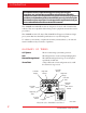
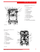
Set-Up Instructions 8 2 10 4 Diagram of Unit’s Components— External View 1 4 11 1. Oil Injection Valves 2. R-134a Hoses 11 3. Scales 4. Oil Injection Bottles 5. 15 Amp Breaker 6. 3 Amp Breaker 2 7. Hose Holders 5 6 7 12 8. RJ45 Upgrade Port 9. Power Cord Receptacle 10. Quick Couplers 11. R-12 Hoses 9 12. External Storage Vessel (ESV) 12 INST 0707 3 Diagram of Unit’s Components— Internal View 6 1. Relays 2. Compressor 5 5 11 3. Vacuum Pump 4. Filter 5. Manifold Block 10 8 6.
Set-Up Instructions INITIAL SET-UP CAUTION! R-134a systems have special fittings (per SAE specifications) to avoid cross-contamination with R-12 systems. Do not attempt to adapt your unit for another refrigerant — system failure will result! Read and follow all warnings at the beginning of this manual before operating the unit. CA UTION! Avoid the use of an extension cord because the CAUTION! extension cord may overheat. However, if you must use an extension cord, use a No.
Set-Up Instructions VACUUM PUMP INITIAL FILL 1. Press VACUUM to get to the VACUUM mode. Press START to go into VACUUM. Set Up Instructions NOTE: The vacuum pump is shipped without oil in the reservoir. Before starting the pump, oil must be added to the pump or damage may occur. 2. Close all manifold valves on the control panel. IMPORTANT ! Formaximum performance,be suretochange thevacuum pumpoil frequently. 3. Remove bolts holding the door closed and open the door. 4.
Operating Guidelines 5. Press START. The unit automatically evacuates the system for 5:00 minutes to remove any air from the external storage vessel (Ensure that all tank valves are open). IF THE SELECTOR SWITCH IS SET TO R-134A: 6. Connect the lowside service coupler to the source tank valve, using the adapter supplied with the unit, when the 5:00 minute evacuation is complete. Open the service coupler and turn manifold valves to RECOVER/VACUUM. IF THE SELECTOR SWITCH IS SET TO R-12: 7.
Operating Guidelines USING THE SELECTION MENU (continued) 4-a. TANK FILL (R-12 Users) NOTE: If using a refillable tank, place the tank upside down and connect the lowside service hose to the vapor valve. Set SELECTOR switch to R-12: 1. Connect the 6" yellow adapter to the end of the low side service hose. 2. Connect the low side service hose to the source tank and open valve. 3. Select TANK FILL from the Selection Menu. 4. Press ENTER. Then press START and the tank automatically refills.
Operating Guidelines USING THE SELECTION MENU (continued) 4-b. TANK FILL (R-134a Users) NOTE: If using a refillable tank, place the tank upside down and connect the lowside service hose to the vapor valve. Set the SELECTOR switch to R-134a: 1. Connect the tank to quick-coupler adapter (supplied with the unit) to the low side service hose. 2. Connect the low side service hose to the source tank and open valve. 3. Select TANK FILL from the Selection Menu. 4. Press ENTER.
Operating Guidelines USING THE SELECTION MENU (continued) FILTER WEIGHT This function is used to show the operator how many pounds of refrigerant have been recovered since the last filter change. 1. Select FILTER WEIGHT from the menu. Press ENTER. 2. The display shows amount of refrigerant recovered since last filter change. 3. If display reads greater than 300 lbs., go to MENU/CHANGE FILTER 4. Press STOP to exit.
Operating Guidelines USING THE SELECTION MENU (continued) MEASUREMENT UNITS 1. Select MEASUREMENT UNITS from the menu. Press ENTER. 2. Toggle between UNITS ENGLISH and UNITS METRIC using the ARROW keys. 3. Press ENTER to select the current choice. LANGUAGE SELECTION The operator can choose between English, Spanish, French, or German. 1. Scroll through the selection menu to LANGUAGE SELECTION and press ENTER. 2.
Operating Guidelines USING THE CONTROL PANEL The control panel has various components that control specific operating functions. MAIN POWER SWITCH — Supplies electrical power to the control panel. DIGITAL DISPLAY — Used on the visual interface between the operator and the machine. LOW SIDE MANIFOLD GAUGE — Connects to an A/C system and shows the system’s low side pressure. HIGH SIDE MANIFOLD GAUGE — Connects to an A/C system and shows the system’s high side pressure.
Operating Guidelines KEYPAD FUNCTIONS In addition to the number keys, the keypad contains special keys that accomplish specific operating functions. • CHARGE — Automatically charges the A/C system with the programmed amount of refrigerant. • CLEAR — Clears indicated data from the unit's memory. • ENTER — Enters programmed data into the unit’s memory. • MENU — Enters the selection menu. • RECOVER — Activates the recovery sequence. • START — Begins a function. • STOP — Terminates a function.
Operating Instructions OPERATING TIPS Follow the recommended service procedure for the containment of R-12 and R-134a. The recovery compressor is not a vacuum pump. The compressor pulls the A/C system to a partial vacuum only. You must use the unit’s vacuum cycle to remove moisture from the A/C system. We recommend a minimum 15-minute vacuum with more time as required by the system manufacturer. This unit is designed to be used with the manifold gauge set built into the control panel.
Operating Instructions RECOVERING REFRIGERANT WARNING Always wear safety goggles when working with refrigerant. Read and follow all warnings at the beginning of this manual before operating theunit. 1. Connect the power cord to the back of the unit and plug into the proper voltage outlet. 2. Turn on the MAIN POWER and empty the oil drain bottle located on the right hand side of the unit. 3. Press RECOVER. 4.
Operating Instructions 10. The unit then goes into automatic oil drain and the display reads OIL DRAINING. Oil draining can require up to 90 seconds to complete. 11. After the oil drain is complete, the display alternates between: RECOVERY COMPLETE CHECK OIL BOTTLE. RECOVERED XXX.XX lbs. RECOVERED XXX.X lbs. 12. Check the oil drain bottle and note the amount of oil that was removed from the A/C system. This is the amount of oil that must be charged into the A/C system after evacuation is complete. 13.
Operating Instructions EVACUATING THE A/C SYSTEM WARNING Always wear safety goggles when working with refrigerant. Use only authorized refillable refrigerant tanks. Read and follow all warnings at the beginning of this manual before operating the unit. In addition to the number keys, the keypad contains special keys that accomplish specific operatingfunctions. IMPORTANT! Youshould evacuate for at least 15 minutes toensure adequatemoisture andcontaminant removal.
Operating Instructions NOTE: If any oil was drained from the system during recovery, DO NOT use the VAC-CHG feature. The oil must be replenished into the A/C system, which is not possible when the VAC-CHG function is used. VACUUM 1. Press ENTER to accept the default evacuation time of 15:00 minutes or enter the desired vacuum time by using the number keys (To enter 10 minutes, press 1 and 10:00 should appear on the display. To enter 1 minute, press 0 then press 1, and 1:00 should appear on the display). 2.
Operating Instructions REPLENISHING A/C SYSTEM OIL Before charging the A/C system, you must replenish any oil removed from the A/C system during the recovery process. 1. Select the correct oil for the A/C system being serviced. Refer to the vehicle manufacturer's service manual. IMPORTANT! You can charge oilthrougheither the low side or high side, or both,depending onthevehicle manufacturer’s recommendation. Justopenthe appropriate manifoldvalveor valves.
Operating Instructions RECHARGING THE A/C SYSTEM WARNING Always wear safety goggles when working with refrigerant. Use only authorizedrefillablerefrigeranttanks.Disconnecthoseswithextreme caution! All hoses may contain liquid refrigerant under pressure. Read and follow all warnings at the beginning of this manual before operating the unit. 1. Press CHARGE. 2.
Maintenance Instructions REPLACING THE FILTER-DRIER Order part #34724 for a replacement filter-drier. The filterdrier on this unit is designed to trap acid and particulates and is formulated to remove water from the refrigerant. You must change the filter-drier to assure adequate moisture and contaminant removal. Typically, you can recycle up to 300 pounds (136 kilograms) of refrigerant between filter changes. CAUTION! For best results, use Robinair filter-driers (part no. 34724).
Maintenance Instructions CHANGING THE VACUUM PUMP OIL For maximum vacuum pump performance, change the vacuum pump oil every 10 hours of operation. 1. Press MENU. 2. Use the ARROW keys to select CHANGE VAC PUMP OIL. 3. Press ENTER. NOTE: Do not connect the service hoses to a vehicle. 4. Ensure that the high side and low side manifold valves are closed and press START. 5. Screen displays OIL CHANGE. 6. Allow the vacuum pump to run until it automatically stops (2 minutes). 7.
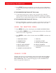
Maintenance Instructions 1 2 6 3 4 5 1 2 3 INST 00709 Diagram of Vacuum Pump 1. 2. 3. 4. 5. 6. Oil Filler Tube Pump Exhaust Oil Fill Port Sight Glass Oil Drain Fitting Inlet INST0760 1. Oil Fill Port 2. Sight Glass 3. Oil Drain CHECKING FOR LEAKS IMPORTANT! Inspecttheunit periodicallyfor leaks.The manufacturer doesnot reimburseforlost refrigerant. Every three months, or as specified by local or state laws, you should check the unit for leaks. 1.
Maintenance Instructions ELECTRICAL PROTECTION If the circuit breaker trips, all power to the unit is lost. Press the circuit breaker button to reset. The circuit breaker is located near the fuse on the back of the unit. GENERAL MAINTENANCE 1. On a regular basis, wipe off the unit with a clean cloth to remove grease, dust or other dirt. 2. Periodically check the internal components for leaks—over time, fittings can loosen as the unit is moved. Open the unit door panel and trace lines with a leak detector.
Replacement Parts The following is a list of replacement parts and accessories you may need to service or maintain your unit. We suggest you keep several filter-driers on hand so you will always be able to change them and complete any recycling job that is in progress.
Replacement Parts List 348002K Replacement Parts Component R-12 Replacement Part Number R-134a Replacement Part Number 96" Red Hose 68396A 63096 96" Blue Hose 68296A 62096 RA17516 RA19409 34724 34724 Compressor RA19735 RA19735 Vacuum Pump RA15425 RA15425 High Pressure Switch RA19427 RA19427 Main Power Switch RA19344 RA19343 Vacuum Switch RA19428 RA19428 Pump Protection Switch RA19429 RA19429 Automatic Expansion Valve RA19592 RA19592 Scale Assembly RA19603 RA19603 Main C
Replacement Parts List 348012K Replacement Parts Component R-134a Replacement Part Number 96" Red Hose 68396A 63096 96" Blue Hose 68296A 62096 RA17516 RA19409 34724 34724 Compressor RA19736 RA19736 Vacuum Pump RA15428 RA15428 High Pressure Switch RA19427 RA19427 Main Power Switch RA19344 RA19343 Vacuum Switch RA19428 RA19428 Pump Protection Switch RA19429 RA19429 Automatic Expansion Valve RA19592 RA19592 Scale Assembly RA19603 RA19603 Main Circuit Board RA19740 RA19740
INST 0717 Flow Diagram 348002K/348012K Cool-Tech Recovery/Recycling/Recharging Unit 27
Inst0718 Wiring Diagram 28 © 2000 Robinair, SPX Corporation
Limited Warranty This product is warranted to be free from defects in workmanship, materials and components for a period of one year from date of purchase. All parts and labor required to repair defective products covered under the warranty will be at no charge. The following restrictions apply: 1. The limited warranty applies to the original purchaser only. 2. The warranty applies to the product in normal usage situations only, as described in the Operating Manual.
CONVERSION TABLE Visit our web site at OZ. LBS. www.robinair.com 0.5 1.0 1.5 2.0 2.5 3.0 3.5 4.0 4.5 5.0 5.5 6.0 6.5 7.0 7.5 8.0 8.5 9.0 9.5 10.0 10.5 11.0 11.5 12.0 12.5 13.0 13.5 14.0 14.5 15.0 15.5 16.0 0.03 0.06 0.09 0.13 0.16 0.19 0.22 0.25 0.28 0.31 0.34 0.38 0.41 0.44 0.47 0.50 0.53 0.56 0.59 0.63 0.69 0.69 0.72 0.75 0.78 0.81 0.84 0.88 0.91 0.94 0.97 1 lb. or call our Toll-Free Technical Support Line at 800-822-5561 in the continental U.S. or Canada.