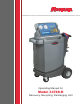
O p e r a t i n g M a n u a l Operating Manual for Model 34788-H Recovery, Recycling, Recharging Unit
Model 34788-H Recovery, Recycling, & Recharging Unit SAFETY DEFINITIONS: Follow all WARNING, CAUTION, and NOTE messages in this manual. These messages are defined as follows: WARNING means you may risk serious personal injury or death; CAUTION means you may risk personal injury, property damage, or unit damage; and NOTEs and OPERATING TIPS provide clarity and helpful information. These safety messages cover situations ROBINAIR is aware of.
Table of Contents Introduction . . . . . . . . . . . . . . . . . . . . . . . . . . . . . . . . . . . . . . . . . . . . . . . . . . 2 Technical Specifications . . . . . . . . . . . . . . . . . . . . . . . . . . . . . . . . . . . . . . 2 Keypad Functions . . . . . . . . . . . . . . . . . . . . . . . . . . . . . . . . . . . . . . . . . . . 3 Glossary . . . . . . . . . . .
Introduction Robinair No. 34788-H is used on R-134a vehicles and is designed to be compatible with existing service equipment and standard service procedures. This unit is a UL-listed, singlepass system that meets SAE specifications for recycled refrigerant. Follow the SAE-J2211 recommended service procedure for the containment of R-134a. The unit includes a 1.5 cfm (42 l/m) Robinair high vacuum pump for fast, thorough evacuation.
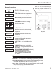
Introduction Keypad Functions START YES START / YES begins or resumes a function, or answers a query. STOP NO STOP / NO terminates or pauses a function, or answers a query. When the unit is not performing a function, pressing the UP or DOWN arrow key adjusts contrast on the digital display. MENU displays the selection menu. MENU ARROWS are used for scrolling through menu items. AUTOMATIC activates a menu that helps the user set up an automatic recover / vacuum / leak test / charge sequence.
Introduction Menu Functions 1. Press the MENU button on the keypad. 2. Press the UP or DOWN arrow key to scroll through the menu choices shown on the second line of the display : SELECT LANGUAGE VERSION X.XX SELECT UNITS MAINTAIN VACUUM OIL MAINTAIN FILTER REFRIG MANAGEMENT MANUAL REFILL ADJUST TANK FILL LVL CALIBRATION CHECK SELECT BEEPER TONE SERVICE MENU HOSE FLUSH DISPLAY TANK INFO SYSTEM FLUSH 3. Press START / YES to make a choice from the menu.
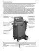
Setup Unpack the Accessory Kit Unpack the accessory kit from the bag, and remove the plastic packaging. The kit consists of • A calibration weight. • Vacuum pump oil, oil filler cap, and tube. • Plastic pouch containing a warranty card (to be completed and mailed), applicable MSDS sheets, a service center listing, and an envelope of Mobile Air Conditioning Society (MACS) information.
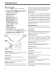
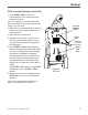
Setup Set Tank Fill Level The operator may either accept the unit’s pre-set default weight of 15 lbs. (6.8 kg) of refrigerant stored in the internal storage vessel (ISV), or change the amount to accommodate the application. Vacuum Pump Fill Port Sight Glass The unit displays LEVEL: 15.00 LBS. ENTER TANK FILL LVL LIMIT: 4 TO 17 LBS. PRESS START / YES TO SAVE 1. Press START / YES to accept the default amount, or use the keypad to enter a desired amount and press START / YES.
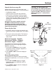
Setup Fill the Internal Storage Vessel (ISV) 1. Press START / YES, and the unit automatically runs a 5-minute vacuum to clear all internal air. Note: The “burping” noise heard during this process indicates air is being purged from the system—this is normal. Low- and High-Side Hoses 2. After the vacuum pump shuts off, connect the fill hose to the liquid connector on a full source tank. 3. Open the source tank valve. Power Cord 4.
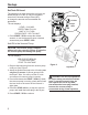
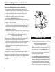
Operating Instructions Recover Refrigerant from a Vehicle 1. Empty the oil drain bottle located on the righthand side of the unit, if necessary, or make note of the current oil level. See Figure 5. 2. Connect the high- and low-side hoses to the vehicle A/C system. 3. Open the coupler valves on the hoses. 4. Press the RECOVER button. Note: The clicking noise heard during the recovery process indicates the solenoid is opening and closing — this is normal. 5.
Operating Instructions Evacuate the A/C System 1. Ensure service hoses are connected, and coupler valves are OPEN. 2. Press VACUUM. 3. Press START / YES to accept the default evacuation time of 10 minutes, or enter the desired vacuum time using the number keys, and press START / YES. CAUTION: The unit pulls a vacuum on the vehicle A/C system to remove air and boil off moisture that may be present in the system.
Operating Instructions Replenish A/C System Oil Oil may be replenished after the charge cycle by using an oil inject tool. Use separate oil inject tools for PAG and POE systems to prevent oil crosscontamination. CAUTION : To prevent damage to equipment, • Use only NEW oil to replace the oil removed during the recycling process. • Charge only the amount of oil that was removed from the A/C system during the recovery process.
Operating Instructions Recharge the A/C System If you are servicing a hybrid vehicle having an electric compressor with POE oil, first perform a brief hose flush procedure to clear the unit of residual PAG oil. CAUTION: Failure to perform this procedure will cause contamination of the hybrid system as well as failure of the compressor. 1. Press CHARGE.
Operating Instructions Recharge the A/C System contd. • When the charge cycle gets close to the weight entered in Step 3, the unit slows down. It will charge, settle, charge again, settle, etc., with the blue/red lights illuminating accordingly. 5. When the charge is complete, the display reads CHARGED XX.XX LBS DISCONNECT HS HOSE DISCONNECT LS HOSE START TO CONTINUE Remove the service hoses from the vehicle A/C system.
Operating Instructions – Automatic The automatic function allows a user to program an automatic recovery, vacuum, leak test, and / or charge sequence. The user may choose to skip any step in the automatic operation during the programming. A total automatic sequence may take an hour to complete. Note: Oil recovered during the recovery cycle can be manually injected by the user before or after the charge cycle using a separate oil inject tool. 1.
Operating Instructions – Automatic 6. The display shows an overview of all the tests that were selected. Press START / YES to begin the automatic sequence. 7. When the sequence is complete, the display shows the amount of refrigerant that was recovered and charged. 8. Close the high- and low-side coupler valves, and remove the service hoses from the A/C system. Press START / YES to clear hoses.
System Flush System Flushing Process This unit provides a method of removing oil by forcing liquid refrigerant through an A/C system, or components of an A/C system. A special flushing adapter, which is available as an accessory, accesses the A/C system at the compressor block. After flushing, the refrigerant is recovered by the unit and filtered by the recycling circuit, returning it to SAE purity levels. A/C systems vary and may require the adapting and flushing of individual components.
System Flush 9. Verify that a flushing filter is correctly installed in the flushing filter housing. Open the isolation valve on the hose. Operating Instructions 1. Press the MENU button on the keypad. 2. Press the UP or DOWN arrow key to scroll through the menu choices until SYSTEM FLUSH is displayed. Press START / YES. 3. Press START / YES to accept the default flush time of 10 minutes, or enter the desired flush time using the number keys. Press START / YES. 4.
Maintenance General Maintenance 1. On a regular basis, wipe off the unit using a clean cloth to remove grease and dirt. 2. Periodically check internal components for leaks; over time, fittings can loosen as the unit is moved. Open the door panel, and trace lines using a leak detector. Check connections on the back of the unit. Tighten any loose fittings or connections you may find. Circuit Electrical Protection Breaker The unit is equipped with a 15 amp circuit breaker on the back panel. See Figure 12.
Maintenance Tank Fill Hose Filter Service The black tank fill hose at the rear of the machine contains a filter that can be cleaned when it appears that refrigerant flow is restricted. When the machine senses low flow, it may display the following message: • SOURCE TANK EMPTY, but yet you know the source tank contains refrigerant, connections are secure, and the source tank valve is open. The cause may be that the tank fill hose filter is plugged. Cleaning the Tank Fill Hose Filter 1.
Maintenance Replace the Filter-Drier The filter-drier is designed to trap acid and particulates, and to remove water from refrigerant. To meet the SAE J-2788 mandate for adequate moisture and contaminant removal, the filterdrier must be replaced after 150 lbs. (68 kg) of refrigerant has been filtered. Therefore, you no longer have a choice—the filter-drier must be replaced. The unit gives a warning when 100 lbs. of the filter capacity has been used; the unit locks down when the 150 lb.
Maintenance Replace the Filter-Drier contd. 5. The display reads PLEASE REPLACE FILTER. Open the rear door of the unit and unscrew the old filter. See Figure 15. 6. Look at the new filter—verify both o-rings are lubricated and correctly located in the grooves. See Figure 16. Thread the new filter into place. Press START / YES. FilterDrier 7. Close the door. Press STOP / NO to exit. The filter-drier replacement is now complete.
Maintenance Change Vacuum Pump Oil Oil Fill Port For maximum vacuum pump performance, change the vacuum pump oil after every 10 hours of operation. (The unit will display a prompt after 10 hours of operation.) 1. Press MENU. Use the arrow keys to select MAINTAIN VACUUM OIL, and press START / YES. The display shows how long the vacuum pump has operated since the last oil change: PUMP OIL TIME X:XX TIME REMAINING X:XX CHANGE OIL? 2. Press START / YES.
Maintenance Scale Calibration Check The calibration check is used to ensure that the unit’s internal scale is always calibrated. During this test, use only the calibration weight that is provided with the unit. 1. Press Menu. 2. Use the arrow keys to scroll to CALIBRATION CHECK. 3. Refer to Figure 18, and verify the magnet on the bottom of the unit is clean. Press START / YES. 4. The display reads ATTACH THE WEIGHT TO THE BOTTOM OF THE MACHINE PRESS START TO CONTINUE 5.
Maintenance Replacement Parts Component Replacement Part No. Filter-Drier Calibration Weight Service Coupler Set (high- and low-side couplers) Service Hose Set (high- and low-side hoses) Vacuum Pump Oil (case of 12 quarts) Vacuum Pump Oil (case of 4 gallons) Maintenance Kit Low-side Hose Flush Storage Port High-side Hose Flush Storage Port Vinyl Dust Cover (optional) Taehicle Database Tank Fill Hose Filter 560826 Rev.
Notes 24
Robinair Limited Warranty Statement Declaración de garantía limitada Robinair Énoncé de la garantie limitée de Robinair Rev. November 1, 2005 This product is warranted to be free from defects in workmanship, materials, and components for a period of one year from date of purchase. All parts and labor required to repair defective products covered under the warranty will be at no charge. The following restrictions apply: 1. The limited warranty applies to the original purchaser only. 2.
Visit our web site at www.robinair.com or call our toll-free Technical Support Line at 800-822-5561 in the continental U.S. or Canada. In all other locations, contact your local distributor. To help us serve you better, please be prepared to provide the model number, serial number, and date of purchase of your unit.To validate your warranty, complete the warranty card attached to the unit, and return it within ten days from date of purchase.