
Instruction Manual


9
R-134a Smart Cart
®
Automatic A/C Charging Station
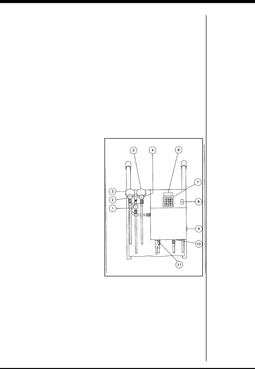
HOW TO USE THE CONTROLS
The charging station has various compo-
nents that control its operating func-
tions.
CAUTION! Do not operate the station
until you have filled the vacuum pump
with oil and removed the exhaust plug
from the pump’s handle, as outlined in
“Preparing the Vacuum Pump.”
1. SYSTEM DISCHARGE Valve — Lets
you depressurize the A/C system.
Connect to a refrigerant recovery
unit — do not vent refrigerant to the
atmosphere.
2. LOW Side Valve — When closed,
isolates the low side of the A/C
system from the station controls.
Note: The manifold is ported so that the
gauges indicate pressure whether or not
the valves are open.
3. LOW Side Compound Gauge — When
connected to the low side of an A/C
system, indicates the system’s low
side pressure.
4. HIGH Side Valve — When closed,
isolates the high side of the A/C
system from the station controls.
5. HIGH Side Pressure Gauge — When
connected to the high side of an A/C
system, indicates the system’s high
side pressure.
6. Display — Shows the time pro-
grammed for vacuum, the weight of
refrigerant programmed for charg-
ing, the control status, and the cycle
of operation. Detailed instructions for
programming the display follow the
next section.
7. Keypad — Accomplishes specific
operating functions, as described in
the next section.
8. MAIN POWER Switch — Supplies
electrical power to the control panel.
9. ACCESSORY Outlet — Provides an
electrical outlet for accessory equip-
ment, such as a thermistor vacuum
gauge. This outlet is energized when
the station is plugged in, and it is
located on the side of the control box.
Note: There is no accessory outlet on the
220V 50Hz model.
10.HEATER Outlet — Provides an
electrical outlet for the refrigerant
tank’s heater blanket. This outlet is
controlled by the MAIN POWER
switch and is energized when the
power is on.
11.PUMP Outlet — Provides an electri-
cal outlet for the vacuum pump. This
outlet is controlled by the logic board.
Additional
Operating
Guidelines
Diagram of Control Components