
Instruction Manual

5
Model 176802K Scavenger™ Recovery Unit
Set Up Instructions
INST0195
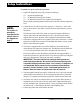
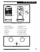
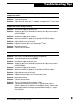
Diagram of Station’s Components
Diagram of Control Panel
INST0116
8. Blue Recovery Hoses
9. Float Cable
10. R-134a Service Coupler
11. Inlet Pressure Gauge
12. Tank Pressure Gauge
13. Control Panel Valve
14. Yellow/Green LED Lights
1. Drain for Drip Pan
2. Black
3
/
8
" Discharge Hose
3. Accumulator Oil Drain
4. Lubricator
5. Battery Clips
6. Regulator
7. Inlet Ports
ROBINAIR
42
53
1
2
3
4
5
6
7
8
10
9
0
0
1
0
1
0
20
20
3
0
3
0
40
40
N
A
3
0
3
0
M
G
G
N
N
I
I
H
H
I
E
D
35
0
35
0
S
S
I
I
A
U
S
P
P
KANTLEAK
ABCO
1
20
1
20
ROBINAIR
ROBINAIR
110
11
0
10
0
100
90
90
5
0
5
0
60
60
7
0
7
0
80
80
N
A
M
0
0
P
S
I
P
S
I
I
D
E
A
U
S
50
0
500
ROBINAIR
ROBINAIR
5
0
5
0
100
100
150
15
0
2
00
2
00
250
250
3
5
0
3
5
0
450
45
0
400
400
3
00
3
00
11 12
13
Inlet Pressure Tank Pressure
Start
Recover