
Specifications

Gas Ignition Controls
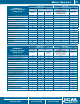
ICM Control Features and Applications Specifications Replaces
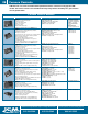
ICM283
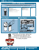
• Hot Surface Ignition (HSI) Module
• Single/Dual rod sensing capabilities
• For gas fired furnaces, boilers and other heating
appliances
• Switch selectable lockout times, ignition trials
• Works with both Natural & LP gas systems
• Diagnostic LED to aid in troubleshooting
• Input voltage: 120 & 24 VAC, 60 Hz
– HSI: 120V, 5A maximum
– Valve: 24V, 2A maximum
– Total: 24V Load = 0.4 + valve load
• Pre-purge time: 32 seconds
• Trial time: 4 or 7 seconds (switch selectable)
• Ignition trials to lockout: 1 or 3 (switch selectable)
• Flame sense: Single rod or dual rod
• Gas type: Natural or LP
•
Honeywell:
S8910U-1000
•
Robertshaw:
HS780
•
White Rodgers:
50E47
50F47
ICM290A
• Universal intermittent pilot gas ignition control
• Provides ignition sequence, flame monitoring
and safety shutoff for single/dual rod intermittent
pilot control applications
• For gas fired furnaces, boilers and other heating
appliances
• Switch selectable pre-purge and ignition trial
times with permanent lock
• Works with or without vent damper connected
• Works with both Natural & LP gas systems
• Control voltage: Line 24V (18-30 VAC), 50-60 Hz
• Anticipator setting: 0.3A plus valve load @ 24 VAC
• Trial for ignition: 15 or 90 seconds (switch selectable)
• LEDs:
– Green status LED provides system status and error
codes
– Yellow flame LED indicates flame presence and
flame strength
• Operating temperatures: Min. ambient temperature
rating of -40°F (-40°C) and max. of 176°F (75°C)
• Relative humidity: 0% to 95% non-condensing
•
Honeywell:
S8610U3009
(and compatible Camstat,
Fenwal, HSC, Penn-
Johnson, Robertshaw and
White Rodgers models)
Furnace Controls
Furnace Control Modules
ICM Control Features and Applications Specifications Replaces
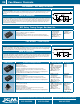
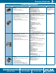
ICM2804
• Hot Surface Ignition (HSI) control board
• Microprocessor-based
• Controls vent motor and blower control
• Monitors limit switch, pressure switch and gas valve
• 100% lockout safety feature
• Compatible with LP or Natural Gas
• Status LED for fault codes to aid in troubleshooting
ENVIRONMENT
• Ambient Temperature
– Operating: -40ºF to 176ºF
– Storage: -40ºF to 185ºF
• Humidity: 5% to 95% R.H. (non-condensing) @ +55ºF
• Vibration: 13.8Hz @ 0.2 Gs for one hour in each
orthogonal axis
ELECTRICAL
• Voltage Range: Line (98-132 VAC) @ 60Hz
• Cool Blower: 20A, 2 HP, 240 VAC
• Heat: 10A, 240 VAC
• Inducer Motor: 4A FLA, 8A LRA @ 120 VAC
TIMING
• Inducer Pre-Purge Time: 1 second
• Heat Blower On Delay: 45 seconds
• Heat Blower Off Delays: 120 or 180 seconds
• Cool Blower On Delay: 1 seconds
• Cool Blower Off Delay: 1 seconds
• Carrier:
CES0110074-00 and
CES0110074-01
Note: This board
functions identically as
the CES0110074-00 and
the CES0110074-01. It
is a replacement of the
CES0110074-01. When
replacing the CES0110074-
00 some quick connectors
have to be changed or added.
EAC-1 and EAC-2 must have
1/4” connectors. COM, SEC-1
and SEC-2 must have 3/16”
connectors.
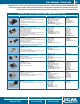
ICM2805A
• Controls gas valve, inducer draft motor, circulating
blower and hot surface ignitor
• Monitors timing, trial for ignition, flame sensing, lockout,
plus pressure, rollout and limit switches.
• Microprocessor-based precision
• Twinning compatible with another ICM2805 furnace
control
• Diagnostic LEDs aid in testing and troubleshooting
• Voltage Range: Line (98 to 132 VAC) @ 60Hz
• Ignitor: 5A, 120 VAC
• Cool Blower: 10A, 2HP, 240 VAC
• Heat: 5A, ½ HP, 250 VAC
• Inducer Blower: 4A, 120 VAC
• Gas Valve: 1A, 24 VAC
• Humidifier Motor: 0.5A, 24 VAC
• Electronic Air Cleaner: 1A, 120 VA
• Nordyne 903106-Kit
(for use with G3, G4,
G5, G6, M2 and M3
furnace modules)
ICM Controls offers the most complete line of HVAC replacement
heating controls. For the most current models, visit us on the web at
www.icmcontrols.com
Gas Ignition Controls
315.233.5266
Phone
All features and specifications subject to change without notice.
Customer Service Fax
315.233.5282
Application Assistance
800.365.5525
Visit www.icmcontrols.com to find all
of our latest products, sell sheets and wiring diagrams
28