
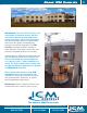
Specifications

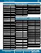

Timers
Ideal for Stagger Starting
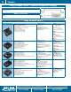
ICM Control Features and Applications Specifications Replaces
ICM150
• UL 873 recognition as compressor controller
• Compressor lockout/anti-short cycle timer
• Integral random start capability
• Random start delay is ideal for stagger-starting multiple units
• Reduces nuisance lockouts/service calls
• Voltage: 18-30 VAC
• 1 amp
• 10 amp inrush
• 40 mA holding current
• Form: SPST, N.O.
• Time delay:
• 6-600 seconds knob-adjustable
• Voltage drop 1.5 V @ 1 amps
• Dimensions: 2” x 2”
• Diversified: ASC-200
• Mars: 32361, 32362
ICM151
• UL 873 recognition as compressor controller
• Compressor lockout/anti-short cycle timer with random start
feature plus:
• Safety switch lockout
• Remote thermostat reset
• Reduces nuisance lockouts/service calls
• Voltage: 18-30 VAC
• 1 amp
• 10 amp inrush
• 40 mA holding current
• Time delay:
• .1-600 seconds knob-adjustable
• Dimensions: 2” x 3”
• Carrier: HN67KZ002
• York: 031-01204-000
To Bypass a Switch or Device During Startup
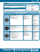
ICM Control Features and Applications Specifications Replaces
ICM175
• Designed to bypass a low pressure switch or other device
during startup
• Ideal for low ambient startups
• Key component for ”winter start” kits
• Helps to reduce nuisance lockouts
• Universal AC voltage operation
• Knob-adjustable time delay
• Epoxy-encapsulated circuitry
• Voltage: 18-240 VAC
• 1 amp maximum
• 40 mA minimum
• 10 amp inrush
• Frequency: 50-60 Hz
• Knob-adjustable time delay: 10-1,000
seconds
• Dimensions: 2” x 2”
• Mars: 32395
• Supco: TD32
Bypass Timers
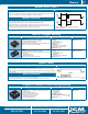
APPLICATIONS TIMING DIAGRAM
”ON delay interval timer,” ”Normally closed delay on make”
Designed to bypass a control or device during startup. Typically used to bypass a low pressure switch
during compressor heat pump startup or to bypass an oil pressure switch upon startup. Helps to eliminate
nuisance lockouts.
MODE OF OPERATION
With power applied to the input, the load energizes immediately and remains energized for the length of
the time delay, regardless of the state of the switch being bypassed.
At the end of the time delay, the condition of the load is determined by the state of the switch.
Random Start Timers
APPLICATIONS TIMING DIAGRAM
”Delay on make/delay on break”
Ideal for use in compressor staging and to stagger-start multiple rooftop units. Helps to reduce power
surges. No need to wait for the 5-minute delay typical of delay on make timers.
0
V
Input
Voltage
Initiate Switch
Closed
Load
Energized
Load
Energized
DOB
Initiate Switch
Open or Loss of Power
D
O
M
D
O
M
0
V
Load
Voltage
Time
Time
* Delay on make time is proportional to selected
Delay on break time.
MODE OF OPERATION
Upon application of power, the delay on make period begins. Once the delay is complete, the unit
energizes. Upon opening of thermostat or loss of power, the load is de-energized and the anti-short
cycle period begins. The compressor will not start again during the delay period.
Safety Switch (ICM151): Upon interruption of power to the compressor via the pressure/limit
switch(es), the compressor will be locked out until the lockout delay expires and the control is reset by
cycling the thermostat OFF then ON, with the safety circuit re-closed.
315.233.5266
Phone
All features and specifications subject to change without notice.
Customer Service Fax
315.233.5282
Application Assistance
800.365.5525
Visit www.icmcontrols.com to find all
of our latest products, sell sheets and wiring diagrams
11