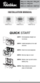
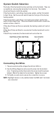
RS4110 RS4220 RS4320 RS5110 RS5220 RS6110 RS6220 RS6320 352-00060-001 Rev B INSTALLATION MANUAL RS4000 Series RS5000 Series RS6000 Series QUICK START STEP 1 Pull backplate straight out to remove STEP 2 Install backplate on the wall and wire STEP 3 Push front onto backplate STEP 4 Remove tape on cover STEP 5 Rotate cover up and remove battery tray STEP 6 Place batteries in tray and place in thermostat 1
Thank you for purchasing a Robertshaw® thermostat. This manual will describe how to install and test the Robertshaw single stage thermostats RS4110, RS5110, RS6110, two stage RS4220, RS5220, RS6220, and three stage* RS4320, RS6320 thermostats. For complete operation instructions, refer to the Robertshaw User Manual. Use the model number to identify your thermostat.
IMPORTANT SAFETY INFORMATION WARNING: • Always turn off power at main fuse or circuit breaker panel before installing, removing, cleaning, or servicing thermostat. • Read all the information in this manual before installing this thermostat. • This is a 24V AC low-voltage thermostat. Do not install on voltages higher than 30V AC. • All wiring must conform to local and national building and electrical codes and ordinances. • This is a dual powered thermostat that will operate on 24V AC or batteries.
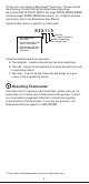
Installing the Robertshaw Thermostat Base NOTE: For new installations, mount the thermostat on an inside wall, five feet above the floor. Do not install behind a door, in a corner, near air vents, in direct sunlight, or near any heat or steam generating fixtures. Installation at these locations will affect thermostat operation. 1. Be certain power is off to the heating and cooling systems. 2. Remove the backplate by placing your finger through the wire opening. Pull the backplate straight out from the body.
System Switch Selection The body of the thermostat has two switches on the backside. They are accessible by removing the backplate from the body. The installer should set these to match the system. If the thermostat is controlling a heat pump system, set the first switch to Heat Pump. Set the second switch based on the type of the backup heating system. If the thermostat is controlling a non-heat pump system, set the first switch to Non-Heat Pump.
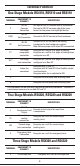
Terminal Function One Stage Models RS4110, RS5110 and RS6110 TERMINAL EQUIPMENT TO CONNECT DESCRIPTION C 24V AC Common Connection For input of 24V AC common side of transformer. Connect to 24V AC common side of the transformer for line power and nightlight feature. RH/R 24V AC Hot Connection Connect to 24V AC hot side of the transformer. RC 24V AC Hot Connection Connect to 24V AC hot side of the cooling transformer for two transformer systems. Note: Remove jumper to Rh when RC is connected.
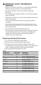
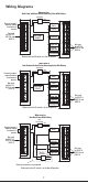
Wiring Diagrams When used as Heat Pump with Cool Active Reversing Valve With Battery Transformer Hot 120 Vac 24 Vac Remove jumper if separate cooling transformer is present. Fan Relay Reversing Valve RH/R RC C Not used for RS4110, RS5110 and RS6110 G O B Compressor Fault Output (24VAC) L Compressor Contactor Y1 W1 Second Stage Cool Second Stage Heat Emer Heat or Third Stage Heat Y2 W2 E Not used for RS4110, RS5110 and RS6110 Make certain the HP switch is in the HP position.
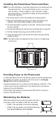
Wiring Diagrams When used as Non-Heat Pump With Battery Backup Transformer Hot 120 Vac 24 Vac Remove jumper if separate cooling transformer is present. Not used for RS4110, RS5110 and RS6110 Fan Relay RH/R RC G O C B Compressor Contactor First Stage Heat Second Stage Cool Second Stage Heat L Y1 W1 Y2 Not used for RS4110, RS5110 and RS6110 W2 E Make certain the HP switch is in the Non-HP position.
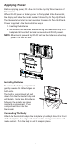
Applying Power Before applying power, fill in the chart in the Pop-Up Wizard section of this manual. When 24V AC power or battery power is first applied to the thermostat, the display will show the model number followed by the Pop-Up Wizard. The thermostat will start normal operation following the Pop-Up Wizard. Power is applied to the thermostat two ways: 1. Installing the batteries. 2.
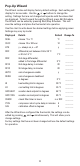
Pop-Up Wizard The Wizard routine will display factory default settings. Each setting will display for ten seconds. Use the or buttons to change the setting. Settings that are not changed will operate with the values that are displayed. To fast forward through the Wizard, press Edit Schedule. The Wizard can be exited by pressing Start/Stop Schedule. This will save the settings and place the thermostat into operation. Use this chart to write down the desired settings before applying power.
Default EnergyStar™ Settings for RS5000 and RS6000 The RS5000 and RS6000 series are programmable thermostats and are preprogrammed with a schedule that is recommended by EnergyStar™. The schedule is designed to lower energy costs year-round.
Press to step through the following: Installation Tests for Single Stage Models Conventional (Non-HP) Demand Terminal First Stage Heat W1 + G* Y1 + G First Stage Cool Y1 + G Y1 + G + O * G, Display Heat Pump (HP) Terminal Display will be off (not displayed) for Non-HP with Gas.
Setting the Mode Press the button to cycle through the available modes. Off OFF Heat Cool Emergency Heat (Multi-Stage Heat Pump units) E Auto changeover (if enabled) A Setting Mode to Emergency Heat The multi-stage thermostats have have an emergency heat capability for heat pump systems. An E will be displayed with the heat symbol . Use emergency heat to turn off the heat pump and turn on a secondary heating source.
To unlock the buttons: 1. Push and hold the and buttons for 5 seconds until the request for password is displayed. 2. Enter the digits for the password by pressing the buttons. Press the move back. and to move to the next digit. Press to 3. When the correct password is set, wait for 5 seconds to unlock the system. 4. If the wrong password is entered the display will flash -- for 5 seconds then return to normal.
Troubleshooting Problem Action Thermostat does not turn on system. Check wiring (see Wiring Diagrams section). System turns on too often. Increase temperature differential (see Pop-Up Wizard section). System fan does not operate properly. Move fan option switch to either gas or electric, to match system (see System Switch Selection section). Thermostat does not display proper room temperature. Check F/C (Fahrenheit/Celsius) setting (see Pop-Up Wizard section).
Five Year Limited Warranty Invensys Controls warrants to the original contractor installer, or to the original consumer user, each new Robertshaw thermostat to be free from defects in materials and workmanship under normal use and service for a period of five (5) years from date of purchase.
RS4110 RS4220 RS4320 RS5110 RS5220 RS6110 RS6220 RS6320 352-00060-001 Rev B INSTALLATION MANUAL RS4000 Serie RS5000 Serie RS6000 Serie COMIENZO RÁPIDO PASO 1 Para retirar la placa posterior tire directamente hacia afuera. PASO 2 Instale la placa posterior sobre la pared y realice las conexiones. PASO 3 Presione el frente contra la placa posterior. PASO 4 Retire la cinta de la tapa. PASO 5 Gire la tapa hacia arriba y retire la bandeja de la batería.
Gracias por comprar un termostato Robertshaw®. Este manual contiene indicaciones para instalar y probar los termostatos Robertshaw de una sola etapa RS4110, RS5110, RS6110, de dos etapas RS4220, RS5220, RS6220, y de tres etapas* RS4320, RS6320. Para ver las instrucciones completas consulte el Manual del Usuario Robertshaw. Use el número de modelo que figura a continuación para identificar su termostato.
ADVERTENCIAS IMPORTANTES SOBRE SEGURIDAD: • Interrumpa siempre el suministro de electricidad desde la llave principal o desde el panel del disyuntor antes de instalar, retirar, limpiar o reparar el termostato. • Lea toda la información que aparece en este manual antes de instalar el termostato. • Este es un termostato de bajo voltaje 24V CA. No instale con voltaje superior a 30V CA.
Instalación de la base del termostato Robertshaw NOTA: En instalaciones nuevas, coloque el termostato en una pared interior, cinco pies por encima del piso. No instale detrás de puertas, en rincones, cerca de corrientes de aire, a la luz directa del sol o cerca de dispositivos que generen calor o vapor. La instalación en esos sitios afectará el funcionamiento del termostato. 1. Verifique que la corriente eléctrica esté desconectada de los sistemas de calefacción y refrigeración. 2.
Mantenimiento de las pilas Cuando las pilas están bajas, el termostato empieza a funcionar en modo baja energía. El modo pila baja tiene dos niveles. • NIVEL 1: Aparece en el visor el ícono de pila baja. • NIVEL 2: Titila intermitentemente el ícono de pila baja que indica que NO FUNCIONARÁ EL SISTEMA. Para elegir la posición de las llaves del sistema El cuerpo del termostato tiene dos llaves en la parte posterior. Puede acceder a ellas retirando del cuerpo la placa posterior.
Función del Terminal Modelos de una etapa RS4110, RS5110 y RS6110 TERMINAL EQUIPO AL QUE SE CONECTA C Conexión común 24VCA RH/R Conexión 24V CA vivo Conecte al lado vivo del transformador de 24V CA. RC Conexión 24V CA vivo Conecte al lado vivo del transformador de refrigeración de 24 V CA en el caso de sistemas con dos transformadores. Nota: Quite el puente a Rh cuando se conecta RC. DESCRIPCIÓN Para entrada de lado común del transformador de 24V CA.
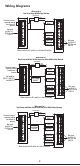
Diagrama de conexiones Cuando se usa como bomba de calor con válvula inversora activada en modo refrigeración con pilas Transformador Vivo 120 Vac 24 Vac Retire el puente si hay un transformador separado para refrigeración No se usa en los modelos RS4110, RS5110 y RS6110 RH/R Relé del ventilador G RC Válvula inversora O Contactor del compresor Y1 C L B Salida falla compresor (24VCA) W1 Refrigeración segunda etapa Verifique que la llave HP esté en la posición "HP".
Diagrama de conexiones Cuando se usa como bomba de no calor con respaldo de pilas Transformador Vivo 120 Vac 24 Vac Retire el puente si hay un transformador separado para refrigeración Relé del ventilador RH/R RC No se usa en los modelos RS4110, RS5110 y RS6110 G O C B L Contactor del compresor Y1 Calefacción de primera etapa W1 Refrigeración de segunda etapa Y2 Calefacción de segunda etapa W2 No se usa en los modelos RS4110, RS5110 y RS6110 E Verifique que la llave HP esté en la posición
Para conectar a la fuente de energía Antes de conectar a la fuente de energía, complete la tabla de la sección Pop-Up Wizard de este manual. Cuando el termostato se conecta por primera vez con la corriente 24V CA o se colocan las pilas, el visor mostrará el número de modelo y luego aparecerá la pantalla del asistente Pop-Up Wizard. El termostato empezará a funcionar normalmente después de la presentación de la pantalla Pop-Up Wizard. Para conectar a la fuente de energía se puede proceder de dos maneras. 1.
Pop-Up Wizard La rutina de la pantalla Wizard mostrará los ajustes que vienen de fábrica por defecto. Cada ajuste aparecerá diez segundos. Use las teclas o para cambiar los ajustes ingresados. Los ajustes que no se modifiquen funcionarán con los valores mostrados. Para avanzar rápido por la pantalla Wizard, pulse la tecla “Edit Schedule” (editar programa”. Puede salir del asistente Wizard pulsando la tecla “Start/Stop Schedule” (iniciar/detener programa).
Ajustes por defecto EnergyStar™ de los modelos RS5000 y RS6000 Las series RS5000 y RS6000 son termostatos programables y están preparados de fábrica con un programa que es recomendado por EnergyStar™. El programa está diseñado para ahorrar energía todo el año.
Si pulsa las teclas repetidamente podrá realizar las pruebas de los modos del sistema. Ver los cuadros siguientes. El visor mostrará los íconos animados correspondientes. Pulse para recorrer lo siguiente: Pruebas de Instalación para Modelos de Una sola Etapa Convencional (No-HP) Bomba de calor (HP) Demanda Terminal Terminal Calefacción primera etapa Calefacción primera etapa W1 + G* Y1 + G Y1 + G Y1 + G + O * G, Visor Visor estarán apagados (no aparecerán) en No-HP/ Gas.
Para ajustar el modo Pulse la tecla para pasar por todos los modos posibles. Off (apagado) OFF Heat (calefacción) Cool (refrigeración) Emergency Heat (Calefacción de emergencia) (Unidades con Bombas de Calor de Etapas Múltiples) E Auto changeover (if enabled) (conmutación automática (si están activadas) A Para fijar el modo calefacción de emergencia Los termostatos de etapas múltiples tienen una característica de calefacción de emergencia para los sistemas de bomba de calor.
Todas las teclas de la parte anterior ahora están bloqueadas y permanecerán bloqueadas hasta que se ingresa la contraseña. Si pulsa cualquier tecla aparecerá el ícono . Para destrabar las teclas: 1. Pulse y mantenga oprimidas las teclas y durante 5 segundos hasta que el sistema le solicite la contraseña. 2. Ingrse los dígitos de la contraseña pulsando las teclas Pulse las teclas y . para pasar al dígito siguiente. Pulse la tecla para ir hacia atrás. 3.
Cuadro del Modo Operacional: Convencional Bomba de calor Bomba de calor (Non-HP) (HP) Elec (HP) Gas Demanda Primera etapa de calefacción W1 + G* Segunda etapa de calefacción W1 + W2 + G* Y1 + G + B Y1 + G + B Y1 + Y2 + G + B Y1 + Y2 + G + B or or Y1 + W2 + G + B Y1 + W2 + G + B Y1 + Y2 + E + G+B Tercera etapa de calefacción N/C E+B or Y1 + W2 + E + G+B Calefacción de emergencia Primera etapa de refrigeración Segunda etapa de refrigeración N/C Y1 + G + O Y1 + G + O Y1 + G Y1 + Y2 + G + O Y1
GARANTIA LIMITADA DE 5 AÑOS Invensys Controls garantiza al instalador contratista original o al usuario original que cada termostato Robertshaw nuevo no tendrá defectos en componentes ni en construcción con el uso y mantenimiento normal durante un período de cinco (5) años desde la fecha de la compra.