
User's Manual

a. The LED on the fuel sensor will quickly flash
yellow four times, then a short pause, followed by
a continuous flashing green. This indicates the
fuel sensor is now ready for the pairing process to
begin.
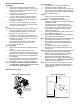
6. While the green LED on the fuel sensor is flashing
continuously, bring the magnet and fuel sensor
together and apart three times in a row within 10
seconds.
a. When the magnet is recognized by the sensor, the
green LED on the sensor will turn off.
b. After a few seconds, the PAR and FUEL switch
LED's will flash slowly indicating the sensor has
been correctly paired.
c. If unsuccessful, the PAR green LED will flash
rapidly and you will need to repeat the sequence
starting at step #3.
Important: Only one fuel sensor may be paired with
a Coordinator. Pairing a 2nd fuel sensor to a
Coordinator will result in the first fuel sensor being
removed from connection with the Coordinator.
Float Installation
1. Drain fuel tank to below 1/2 full reading on site
gauge. Remove existing float and gasket.
2. Install new gasket on float assembly.
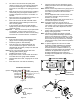
3. Insert the “bent arm” float assembly with the
correct orientation see figure 6. Secure float
assembly with the 4 bolts (1/4-28) to the tank and
torque to 20-50 in lbs.
Note: Do not over torque bolts because this could
damage gasket and the gauge.
4. Installing fuel sensor on tank.
a. Empty tank to below ½ full and clean the surface
of the tank where the gauge will be installed.
b. Orientate fuel sensor with “1/2”gauge at the 12:00
position.
c. Place fuel sensor over float arm assembly.
d. Fully seat sensor onto the assembly by gently
tapping around the sensor face with a plastic or
rubber hammer.
Note: Sensor must be fully seated on the gauge prior to
securing the sensor with supplied screws. Do not
use screws to pull sensor onto the float arm
assembly.
e. Use the supplied screws to secure sensor onto
the float arm assembly. Torque screws to
between 12-15 in-lbs.
f. Fill tank with diesel fuel and confirm there are no
fuel leaks and repair if necessary.
Note: If fuel tank is less than 10% full at time of
installation, it may not respond to the float level.
Use magnet to move the gauge needle towards
the “1/4” full mark until it responds to the float
level position.
5. Confirm fuel level reading on controller HMI
display under gauge menu.
Note: This device complies with Industry Canada
licence-exempt RSS standard(s). Operation is
subject to the following two conditions: (1) This
device may not cause interference, and (2) This
device must accept any interference, including
interference that may cause undesired operation
of the device.
Note: Le présent appareil est conforme aux CNR
d'Industrie Canada applicables aux appareils
radio exempts de licence. L'exploitation est
autorisée aux deux conditions suivantes : (1)
l'appareil ne doit pas produire de brouillage, et (2)
l'utilisateur de l'appareil doit accepter tout
brouillage radioélectrique subi, même si le
brouillage est susceptible d'en compromettre le
fonctionnement"
Coordinator Selections
(Power / Diagnostic) PWR • • FUEL
(Pairing) PAR • • TEMP (Temperature)
(Zone1) Z1 • • GUI (Graphical User Interface)
(Zone2) Z2 • • 01 (Option 1)
(Zone3) Z3 • • UN (Unpair)
(Door) DR • • DI (Diagnostic)
Figure 3
Figure 6
Square
Round
Up
Figure 5
Magnet
Pairing Target
PWR
COM
Z1
Z2
Z3
DR
FUEL
TEMP
GUI
O1
UN
DI
Coordinator Module
Coordinator
Module Switch
Figure 4