
User's Manual
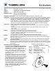

Fuel Level Alarm
4. Fuel Level Alarm wiring – applicable only to
controllers with fuel level alarm input.
a. For systems that have a system level voltage (12-
14V) fuel alarm input without a variable fuel level
input, connect the Coordinator output wire labeled
FLA to the alarm circuit.
Pairing
Pairing is the process of identifying the fuel
sensor to the CargoLink network.
Important: Keep all sensors away from the
magnets for at least 60 seconds before beginning
the pairing process.
1. Bring all sensors to be paired directly to the
coordinator module. The pairing activity should
occur within 10 feet of the coordinator module
especially when multiple systems are being
installed concurrently.
2. Verify the red PWR (Power) LED is illuminated on
the Coordinator. See figure 3.
3. Press and release the switch on the Coordinator
until the FUEL LED is illuminated.
Note: Repeated presses of the switch will cycle through
all selections before starting over at the top.
4. Once FUEL is selected, press and hold the
switch again until the green PAR (Pairing) LED
illuminates.
a. One green and two red LED’s will now be
illuminated on the module indicating it is in the
pairing mode.
NOTE: If no action is taken within 30 seconds, the green
PAR LED on the module will begin flashing
rapidly for 8 seconds and then go out. Repeat
step 4 to restart the pairing procedures.
5. With the three LED's (PWR, FUEL & PAR)
illuminated on the coordinator, bring the supplied
magnet and sensor together quickly two times
and then remove the magnet.
Note: The correct orientation of the fuel sensor to the
magnet must be followed or the pairing process
will not work. See figure 5 for proper pairing
target alignment.
INSTALLATION PROCEDURE:
SR-2 & SR-3
1. Wiring the Coordinator to SR-2 & SR-3 Fuel
sensor input – if wiring to an SR-4, go to step 2, if
wiring to a control that only accepts a fuel level
alarm input, go to step 7.
a. Locate the “FLL” wire at connector J3 pin 23 on
the SR-2 or SR-3 controller.
b. Cut FLL, leaving 102 mm (4”) of wire from the
connector. Use a single sided crimp connector
and cap the cut wire no longer connected to the
controller. Go to Step 3.
c. If no wire is connected to pin 23, use included
terminal (41-2457) and crimp on FLS wire. Insert
into J3 pin 23. Go to Step 3b.
SR-4
2. Wiring the Coordinator to SR-4 fuel sensor input
a. Locate the “FUEL-01” wire at the 3 wire option
harness located at the bottom of the control
cabinet or at connector J1 pin 2.
b. Cut FUEL 01, leaving 102 mm (4”) of wire from
the connector. Use a single sided crimp connector
and cap the cut wire no longer connected to the
controller. Go to Step 3.
c. If no wire is connected to pin 2, use included
terminal and crimp on FLS wire. Insert into
J1 pin 2. Go to Step 3b.
ALL SR Controls
3. Wiring the Coordinator to the controller & Menu
Setup.
a. The fuel level sensor output wire from the
Coordinator is labeled as FLS. Connect the FLS
wire to the FLL or FUEL-01 connections identified
above using a crimp connector supplied with the
Coordinator kit.
b. Enter the guarded access menu on the controller
and change the Fuel Level sensor input type to
“solid state”. Proceed to the pairing operation.
Note: The Fuel Level Sensor input type must be set
to “Solid State”. Setting it to “Float” will result
in inaccurate fuel level readings.
End SR Controller wiring
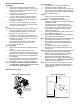
SR-2 & SR-3 Controller wiring
Locate the FLL
wire and cut 4”
from connector
Figure 1
Figure 2
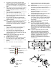
FUEL-01
Coordinator
FLS
Unit
Harness
Controller
SR-4 Controller Wiring
Cap
cut
wire