
Service manual

TF-SERIES INSTALLATION, OPERATION AND SERVICE MANUAL
46
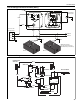
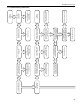
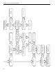
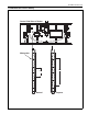
11.4 Ladder Diagram
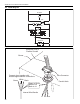
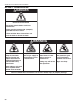
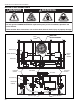
11.5 Electrical Connection to the Burner
GROUND
POWER
SENSE
SPARK
VALV E
L1 L2
BLOWER
PRESSURE SWITCHES
IGNITION MODULE
GAS VALVE
ELECTRODE
ELECTRODE
120V
24V
GAP GAP
LIGHT
Conduit Hole
Wire Connector
Burner
Internal Wire Bundle
L1
L2
Gnd.
Connect wires together with
suitable approved wire connections.
Green to Gnd.
White to L2
Black to L1
Electrical Cord or
Flexible Conduit
Green
White
Black