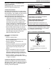
Combat ® UHD-Series Tubular Duct Furnace (Low Profile Range) Installation, Operation & Service Manual Models UHD[X][S][R] 75, 100, 125 WARNING Improper installation, adjustment, alteration, service or maintenance can result in death, injury or property damage. Read the Installation, Operation and Service Manual thoroughly before installing or servicing this equipment. Installation must be done by a contractor qualified in the installation and service of gas-fired heating equipment or your gas supplier.
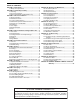
TABLE OF CONTENTS SECTION 1: Heater Safety...................................................... 1 1.1 Manpower Requirements ............................................. 1 SECTION 2: Installer Responsibility ..................................... 2 2.1 Wall Tag ....................................................................... 2 2.2 Corrosive Chemicals.................................................... 2 2.3 National Standards and Applicable Codes ..................
TABLE OF FIGURES Figure 1: Clearances to Combustibles ...................................... 3 Figure 2: Air Flow Direction....................................................... 7 Figure 3: Suspension Methods ................................................. 8 Figure 4: Shelf-Mounting Methods ............................................ 9 Figure 5: Wall Shelf Mounting and Suspension ........................ 9 Figure 6: Vent and Roof Detail ................................................
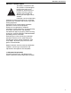
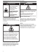
SECTION 1: HEATER SAFETY SECTION 1: HEATER SAFETY Your Safety is Important to Us! This symbol is used throughout the manual to notify you of possible fire, electrical or burn hazards. Please pay special attention when reading and following the warnings in these sections. Installation, service and quarterly inspection of heater must be done by a contractor qualified in the installation and service of gas-fired heating equipment.
UHD LOW PROFILE DUCT FURNACE INSTALLATION OPERATION AND SERVICE MANUAL SECTION 2: INSTALLER RESPONSIBILITY The installer is responsible for the following: • To install the heater, as well as the gas and electrical supplies, in accordance with applicable specifications and codes. Roberts-Gordon recommends the installer contact a Local Building Inspector or Fire Marshal for guidance.
SECTION 3: CRITICAL CONSIDERATIONS SECTION 3: CRITICAL CONSIDERATIONS 3.1 Basic Information UHD[X][S][R] heaters have automatic ignition burners for ON/OFF operation only. 3.2 Manufactured Units Gas-fired, power-vented duct furnace with tubular heat exchanger. Units shall have a minimum of 82% thermal efficiency. The standard unit shall consist of a non-separated combustion design with an aluminized heat exchanger.
UHD LOW PROFILE DUCT FURNACE INSTALLATION OPERATION AND SERVICE MANUAL 3.6 Ventilation 3.8 Electrical Supply WARNING WARNING Carbon Monoxide Hazard Heaters may be installed vented or unvented. Vented heaters must be vented outdoors. Unvented heaters must be installed in buildings with ventilation rates as per section 6.4. Failure to follow these instructions can result in death or injury.
SECTION 4: NATIONAL STANDARDS AND APPLICABLE CODES SECTION 4: NATIONAL STANDARDS AND APPLICABLE CODES 4.1 Gas Codes The type of gas appearing on the name plate must be the type of gas used. Installation must comply with national and local codes and requirements of the local gas company. United States: Refer to NFPA 54/ ANSI Z223.1 latest revision, National Fuel Gas Code. Canada: Refer to CSA B149.1 Natural Gas and Propane Installation Code. 4.
UHD LOW PROFILE DUCT FURNACE INSTALLATION OPERATION AND SERVICE MANUAL 4.6 High Altitude These heaters are CSA-approved (without modifications) for installations up to 2000' (610 m) in US and Canada. CSA approved heaters installed above 2000' (610 m) must be de-rated. For installations above 2000' (610 m) in US, consult factory for information on burner derating. For installations from 2000' (610 m) to 4500' (1370m) in Canada, high altitude conversion kits are available.
SECTION 5: DUCT HEATER INSTALLATION SECTION 5: DUCT HEATER INSTALLATION 5.1 General To connect the inlet and outlet ducts to the heater, Duct-Mate or similar flanges may be slid over the duct connector flanges supplied on the unit and secured with screws. The connection to the duct then can be made using the Duct-Mate clips. The ducts must have removable access panels upstream and downstream of the heater.
UHD LOW PROFILE DUCT FURNACE INSTALLATION OPERATION AND SERVICE MANUAL 5.2 Shelf Mounting and Suspension WARNING Do not locate the gas or electrical supply lines directly over the path of the flue products from the heater. Crush Hazard Use 3/8" threaded rod minimum. Failure to follow these instructions can result in death, injury or property damage. Four suspension points (3/8" nuts) are located on the top of the heater. Drop rods must be 3/8" diameter mild steel.
SECTION 5: DUCT HEATER INSTALLATION Figure 4: Shelf-Mounting Methods Existing cabinet screws must be re-used. Description Shelf Mounting Bracket Kit Shelf Mounting Bracket Screw #10 x 1/2" Type AB Phil HWH Z Shelf Mounting Brackets Part Number 12011000K 11111510 Qty.
UHD LOW PROFILE DUCT FURNACE INSTALLATION OPERATION AND SERVICE MANUAL SECTION 6: VENTING WARNING Carbon Monoxide Hazard Heaters may be installed vented or unvented. Vented heaters must be vented outdoors. Unvented heaters must be installed in buildings with ventilation rates as per section 6.4. Failure to follow these instructions can result in death or injury. 6.1 Changing Vent and Air Intake Orientation The heater is sold with rear horizontal vent and air intake connections as standard.
SECTION 6: VENTING Vents and air intakes must be adequately supported so that the heater does not bear the weight of the pipes. For vent termination See Page 13, Figure 6 through Page 16, Figure 11. 6.3.1 Standard Vented Heaters (Models UHD[X][R] 75 - 125) The vent must be fitted with a low resistance terminal. See Page 13, Figure 6 through Page 13, Figure 7. Standard vented heaters do not allow outdoor air intake for combustion air. 6.3.
UHD LOW PROFILE DUCT FURNACE INSTALLATION OPERATION AND SERVICE MANUAL and additional sealing measures (high temperature silicone at all seams) are required. The entire vent should be insulated with foil faced fiberglass insulation (1/2" thick, 1-1/2# density minimum). 6.7.1 Maximum Vent Lengths Model UHD[X][S][R] 75, 100, 125 40 ft (12.2 m) 35 ft (10.7 m) 30 ft (9.1 m) 25 ft (7.6 m) 20 ft (6.1 m) Number of Elbows 1 2 3 4 5 4. 5. 6. 6.8 Vent Material Vent material may be single wall 26 ga.
SECTION 6: VENTING Figure 6: Vent and Roof Detail Figure 7: Standard Vented Heater - Vertical and Horizontal Vent Termination Model UHD[X][R] 75 - 125 Vent Diameter 4" (10 cm) Part Number 90502102 13
UHD LOW PROFILE DUCT FURNACE INSTALLATION OPERATION AND SERVICE MANUAL Figure 8: Standard Vented Heater - Common Vertical Vent Termination 14
SECTION 6: VENTING Figure 9: Separated Combustion Heater - Vertical and Horizontal Vent Termination Model UHD[X]S[R] 75 - 125 Air Intake & Vent Diameter 4" (10 cm) Part Number 90502102 Figure 10: Concentric Vent Box ace t airsp s) ) m c er /4" (6 y oth ter, 1 alent. (B e m ) dia or equiv 0 cm 4" (1 odel RV f o irk M piece One vent. Selk “B” ype Toward Outside Seal joint between single wall and Type B vent with silicone sealant.
UHD LOW PROFILE DUCT FURNACE INSTALLATION OPERATION AND SERVICE MANUAL Figure 11: Concentric Vertical and Horizontal Vent Termination - Separated Combustion Heater Description Concentric Vent Kit Concentric Vent Box Top & Side Assembly Concentric Vent Box Bottom Assembly Screw #6 x 3/8 Self Drilling 4" (10 cm) Vent Terminal with Baffle Plate 6" (15 cm) Combustion Air Terminal 16 Part Number UHVK1 90504113 90504112 91119100 90502102R 90502103 Qty.
SECTION 7: AIR SUPPLY SECTION 7: AIR SUPPLY 7.1 Separated Combustion Installation When installed as a separated combustion heater (UHD[X]S[R]), the air for combustion is drawn in from outside the building. 7.2 Unvented Installation It is important to ensure that there is adequate fresh air supply at all times for both combustion and heating requirements in accordance with local and national codes.
UHD LOW PROFILE DUCT FURNACE INSTALLATION OPERATION AND SERVICE MANUAL SECTION 8: GAS PIPING Fire Hazard Connect gas supply according to Figure 12. Do not use gas supply pipe and electrical connections to support the heater’s weight. Gas can leak if not installed properly. Failure to follow these instructions can result in death, injury or property damage. A gas meter is connected to the service pipe by the gas supply company.
SECTION 9: WIRING SECTION 9: WIRING WARNING All heaters are equipped with thermostat connections suitable to power a 24 V thermostat. Heater must be wired and electrically grounded in accordance with local codes. In the absence of local codes in accordance with: United States: refer to National Electrical Code NFPA 70 - latest revision; Canada: refer to Canadian Electrical Code CSA C22.1 Part I - latest revision. ® Electrical Shock Hazard Disconnect electrical and gas supply before servicing.
UHD LOW PROFILE DUCT FURNACE INSTALLATION OPERATION AND SERVICE MANUAL 9.
SECTION 9: WIRING 9.
UHD LOW PROFILE DUCT FURNACE INSTALLATION OPERATION AND SERVICE MANUAL 9.5 Electrical Connection to the Heater Flexible Conduit BX Connector Burner Connect wires together with suitable approved wire connectors. L1 L2 Ground Green to Ground White to L2 Black to L1 Black White Green Junction Box IMPORTANT: Junction box is not provided with heater. Conduit can also be attached directly to heater with wire junction made within the heater cabinet.
SECTION 10: OPERATION AND MAINTENANCE SECTION 10: OPERATION AND MAINTENANCE WARNING Explosion Hazard Installation, service and annual inspection must be done by a contractor qualified in the installation and service of gas-fired heating equipment or your gas supplier. 10.2 Begin Start-Up 10.2.1 Before Operating the Heater To ensure that all the controls are in safe working order, operate the heater for the first time with the isolating gas valve turned off and power supply turned on. 1.
UHD LOW PROFILE DUCT FURNACE INSTALLATION OPERATION AND SERVICE MANUAL Figure 13: Automatic Burner Control Sequence Burner Sequence for Ignition Control START RUN SHUT DOWN Thermostat 24 V Flue Blower 30 Seconds Purge* Pressure Switch P C 30 Seconds Post NO NC ts = 10 Seconds Ignition Spark Start Gas Valve Flame Signal *Purge time begins at pressure switch change over. Required Incoming Signals Signals Output By Control If at any stage the flame fails, the control will retry for ignition.
SECTION 10: OPERATION AND MAINTENANCE 10.2.2 Start-Up the Gas Valve (All Gases) 10.2.2.1 Check Burner Gas Pressure 1. Remove the plug in the outlet (burner) pressure test point and connect a pressure tap and a manometer. 2. With the burner firing, measure the pressure on the manometer.
UHD LOW PROFILE DUCT FURNACE INSTALLATION OPERATION AND SERVICE MANUAL SECTION 11: USER INSTRUCTIONS WARNING 11.3 Common User Controls 11.3.1 Manual Reset Limit Switch WARNING Explosion Hazard Installation, service and annual inspection must be done by a contractor qualified in the installation and service of gas-fired heating equipment or your gas supplier. Turn off gas and electrical supplies before performing service or maintenance.
SECTION 11: USER INSTRUCTIONS 11.4.2 To Turn Heater Off Set the thermostat to the "OFF" position. The burner will turn off immediately. To restart, turn the thermostat above room temperature. 11.5 Simple Troubleshooting Some possible reasons for the heater not operating are: 1. Gas supply not "ON". 2. Electricity supply not "ON". 3. The time and/or temperature controls are not "ON". 4. A limit switch may have operated.
UHD LOW PROFILE DUCT FURNACE INSTALLATION OPERATION AND SERVICE MANUAL SECTION 12: SERVICING WARNING Explosion Hazard Installation, service and annual inspection must be done by a contractor qualified in the installation and service of gas-fired heating equipment or your gas supplier. Turn off gas and electrical supplies before performing service or maintenance. Failure to follow these instructions can result in death, injury or property damage. 12.
SECTION 12: SERVICING 12.7 Maintenance Checklist WARNING Installation Code and Annual Inspections: All installations and service of ROBERTS GORDON equipment must be performed by a contractor qualified in the installation and service equipment sold and supplied by Roberts-Gordon and conform to all requirements set forth in the ROBERTS GORDON manuals and all applicable governmental authorities pertaining to the installation, service and operation of the equipment.
UHD LOW PROFILE DUCT FURNACE INSTALLATION OPERATION AND SERVICE MANUAL Gas Line and Shut-off Valves Check for gas leaks. Burner Observation Window Make sure it is clean and free of cracks or holes. See Page 18, Section 8. Clean and replace as required. Flue Blower Scroll, Wheel Compressed air or a vacuum cleaner may be used to clean dust and dirt. and Motor Inshot Burners and Clear obstructions (even spider webs will cause problems). Orifices Carefully remove any dust and debris from the burner.
SECTION 13: TROUBLESHOOTING SECTION 13: TROUBLESHOOTING 13.1 General WARNING Explosion Hazard Installation, service and annual inspection must be done by a contractor qualified in the installation and service of gas-fired heating equipment or your gas supplier. START Are gas & electrical supplies on? No Turn off gas and electrical supplies before performing service or maintenance. Turn on supplies. Failure to follow these instructions can result in death, injury or property damage.
UHD LOW PROFILE DUCT FURNACE INSTALLATION OPERATION AND SERVICE MANUAL 13.2 Troubleshooting For Automatic Ignition Burner Systems START Are gas & electrical supplies on? No Turn on supplies. No Turn on controls. Yes Are external controls (i.e. Thermostat) on? UHD 75: Press in reset button on manual reset limit switch. UHD 100 - 125: Wait Yes 10 - 15 minutes for limit switch to cool.
SECTION 13: TROUBLESHOOTING 13.3 Troubleshooting for Flame Supervision System To measure flame current, connect a 0 - 50 μA DC meter in series with the flame probe. If the meter reads negative values, then reverse the test leads. START Connect a DC ammeter in series with the flame probe. Is the flame present and at least 1 μA DC flame current? No Use General Troubleshooting section to trace the fault.
UHD LOW PROFILE DUCT FURNACE INSTALLATION OPERATION AND SERVICE MANUAL 13.4 Troubleshooting for Gas Valves START Is gas pressure at inlet of the valve correct for gas type? Note pressure found. No Fault elsewhere. Correct pressure problem. No Valve or ignition control faulty. Replace with one of correct type. No Valve faulty. Replace with one of correct type. No If problems persist, contact Roberts-Gordon LLC at www.rg-inc.
SECTION 14: REPLACEMENT PARTS SECTION 14: REPLACEMENT PARTS Burner Components All serviceable burner parts are accessed by the door on the side of the heater. Remove the sheetmetal screws. WARNING 14.1 Gas Valve Remove the gas supply pipe at the heater inlet. Follow steps in Section 14.2 and Section 14.2.1 to remove gas valve/manifold. Replace in reverse order. Verify that the gas flow direction of the valve is correct. Use a minimum amount of gas seal on the thread joint.
UHD LOW PROFILE DUCT FURNACE INSTALLATION OPERATION AND SERVICE MANUAL 14.2 Burner Compartment Burner Compartment Cover The burner compartment is a sealed compartment. Following any work, re-seal the compartment with the gas pipe rubber seal fully in place and all screws fitted and tight. Viewing port for flame probe Flame Probe Ignition Electrode Remove flexible air duct from spigot NOTE: Separated combustion model shown. Remove screws and pull off burner cover 14.2.
SECTION 14: REPLACEMENT PARTS 14.3 Ignition Electrode and Flame Probe Inshot Burners Manual Reset Limit Switch (Position may vary.) Flame Probe Flame Probe Limit Switch Burner Compartment Front Views Ignition Electrode Ignition Electrode .120 (3 mm) spark gap Inshot Burners To replace the electrode or flame probe, remove the electrical lead and screw. Pull out from mounting. Refit in reverse ensuring that the gap to burner is as shown in the front view of the burner compartment.
UHD LOW PROFILE DUCT FURNACE INSTALLATION OPERATION AND SERVICE MANUAL 14.5 Flue Blower Vertical Installation To remove the blower, remove screws securing the fan and mounting plate to the vent box. Intake & Exhaust Covers Mounting Plate to Vent Box fixing screws Air Intake Adaptor Gaskets Vent Box Refit in reverse order. To change the vent and air intake orientation from back to top, remove the blower and mounting plate as above. Remove intake (if applicable) and exhaust covers from top of the heater.
SECTION 14: REPLACEMENT PARTS 14.6 Pressure Switch Pull off 3 way connector. Spring open plastic clips of mounting cradle. Replace with correct type of pressure switch for model. The pressure switches are color coded for each pressure setting. Carry out a start-up after working on or changing a pressure switch. See Page 23, Section 10.
UHD LOW PROFILE DUCT FURNACE INSTALLATION OPERATION AND SERVICE MANUAL SECTION 15: SPECIFICATIONS 15.1 Dimension Data TOP VIEW 17.63" (45 cm) B 4 x 3/8" Captive Nuts Provided Air Intake (UHD[X][S][R] only; Optional Position) 18.25" (46 cm) 16.63" (42 cm) Flue (Optional Position) 6" (15 cm) C 6.75" (17 cm) B E SIDE VIEW REAR VIEW 20.25" ( 51 cm) Flue B E D 6.75" (17 cm) 6" (15 cm) A A Air Intake 6" (UHD[X][S[]R] (15 cm) only) Thermostat Connection Gas Supply Electrical Supply 1.
SECTION 15: SPECIFICATIONS 15.2 General Technical Data Table Model UHD[X][S][R] 75 UHD[X][S][R] 100 UHD[X][S][R] 125 A 1 2 2 CFM 850 950 1020 °F ( °C) 68 (20) 78 (26) 92 (33) Heat Exchanger Pressure Drop @ Minimum Air Volume in wc 0.06 0.05 0.06 Maximum Air Volume CFM 2650 3660 4750 °F ( °C) 22 (-6) 22 (-6) 20 (-7) in wc 0.36 0.55 0.
UHD LOW PROFILE DUCT FURNACE INSTALLATION OPERATION AND SERVICE MANUAL 42
® ® SECTION 16: ROBERTS GORDON COMBAT UHD-SERIES WARRANTY ® ® SECTION 16: ROBERTS GORDON COMBAT UHD-SERIES WARRANTY The ownership of the ROBERTS GORDON COMBAT ROBERTS GORDON WILL PAY FOR: ® ® Within 24 months from date of purchase by buyer or 27 months from the date of shipment by Roberts-Gordon (whichever comes first), replacement parts will be provided free of charge for any part of the product which fails due to a manufacturing or material defect.
® Wa r m Air Heating OWNER WARRANTY REGISTRATION CARD Mail or Fax to: Roberts Gordon LLC • 1250 William Street, P.O. Box 44 • Buffalo, NY 14240-0044 • Phone: 716-852-4400 • Fax: 716-852-0854 Toll Free: 800-828-7450 • www.rg-inc.
Attach this information to the wall near the ROBERTS GORDON® heater ® Read the Installation, Operation and Service Manual thoroughly before installation, operation or service. WARNING OPERATING INSTRUCTIONS 1. STOP! Read all safety instructions on this information sheet. 2. Open the manual gas valve in the heater supply line. 3. Turn on electric power to the heater. 4. Set the thermostat to desired setting (above ambient temperature). The automatic starting sequence begins. TO TURN OFF THE HEATER 1.