
Service manual

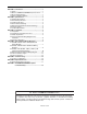


TABLE OF FIGURES
Figure 1: Panel Layout .............................................................. 3
Figure 2: Terminal Block Guide................................................. 4
Figure 3: Mounting Hole Layout................................................5
Figure 4: System Configuration.................................................6
Figure 5: External Wiring Diagram ROBERTS GORDON
®
EP-100 and EP-201 120 V 1 Ø Pump ...................... 7
Figure 6: External Wiring Diagram ROBERTS GORDON
®
EP-100, EP-201 or EP-301, 230 V 1 Ø Pump ..........8
Figure 7: External Wiring Diagram ROBERTS GORDON
®
EP-203 or EP-303, 208 - 230 V (or 460 V)
3 Ø Pump............................................................... 10
Figure 8: External Wiring Diagram ROBERTS GORDON
®
EP-100 or EP-201 120 V 1 Ø Pu mp with
Outside Air Blower................................................. 12
Figure 9: System Control Troubleshooting Chart .................... 15
Figure 10: System Control Internal Components Diagram ...... 16