
Service manual


SECTION 6: MOTOR WIRING
15
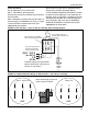
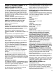
6.3 EP-303 Wiring
The EP-303 motor can be wired for 3 Ø,
208 V - 230 V/460 V, 60 Hz operation.
Do not directly connect the controller relay terminals to
the pump motor.
When controlled by a System Control or BZC 700, use
starter package P/N 10050010. See Page 15, Figure
14. See Controller Installation Manual for (P/N
10091601NA) wiring details.
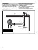
Wire the pressure switch per the appropriate wiring
diagram in the Controller Installation Manual.
If using ROBERTS GORDON
®
ULTRAVAC™ controls,
the power to the EP-303 pump is not supplied by the
controller. Power is supplied by a separate circuit and is
switched by the controller via the Variable Frequency
Drive (VFD) 208 - 230 V only. See the ROBERTS
GORDON
®
ULTRAVAC™ Installation Manual (P/N
10081601NA) for wiring details.
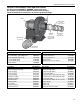
FIGURE 14: EP-303 208 V - 230 V (or 460 V) 3 Ø Pump Starter Wiring Diagram
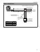
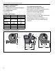
FIGURE 15: Impeller Direction Wiring for EP-303 (208 V - 230 V/460 V) 3 Ø Pump
L3
L1
L2
120 V
1 Ø
60 Hz
from
control
panel
208 V - 230 V
(or 460 V)
3 Ø
60 Hz
The power supply for each
pump must be separate
from the controller supply
Do not directly connect the
controller relay terminals to the
pump motor
Pump
M
OL
153
264
264
95
96
Starter package P/N 10050010
rated for the EP-303 pump motor
Individual supply for pump rated for
total full load current (See Page 22,
Section 10.2 for details).
208 V - 230 V 3 Ø
LINE
10
11
12
4
5
6
7
8
9
1
2
3
460 V 3 Ø
LINE
10
11
12
4
5
6
7
8
9
1
2
3
Note: Interchange any two line
leads to reverse rotation.