
Service manual

EP-300 SERIES PUMP INSTALLATION, OPERATION AND SERVICE MANUAL
12
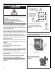
5.4 Condensate Tee Assembly
The condensate tee assembly is composed of a tee,
draincap, and condensate trap.
If the system is designed in the condensing mode, then
the installation of a condensate tee assembly is
required. The condensate tee assembly, must be
installed on the inlet side of the pump assembly if there
is horizontal venting of the pump, See Page 12, Figure
10.
A condensate drain on the discharge side is required
if there is vertical venting of the pump or if there is a
vertical rise in the discharge line away from the
pump. See Page 13, Figure 11.
The condensate tee assembly in the discharge line
can be eliminated if the discharge line is horizontal
through the wall and pitched down at least 1/4" per
10' (6 mm per 3 m). This arrangement will permit
drainage of condensate through the pump and out-
side via the horizontal (pitched) discharge line.
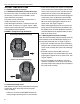
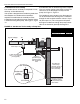
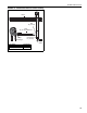
FIGURE 10: Condensate Tee Assembly at Pump Inlet
Must be connected
to a drain system
in accordance with
local codes.
flow
Condensate
Valve
Assembly
3/4" female
3/4" female
36" Minimum
vertical drop
between pump
and condensate
valve assembly.
Copper or
galvanized pipe
between pump
and condensate
valve.
Wall
Tee
Drain Cap
System Tailpipe
1" NPT threaded hole.
Use 1" x ¾" reducer.
(not supplied)
Description Part Number
Tee 4" (10 cm) 01330203
Tee 6" (15 cm) 01330204
Drain Cap 4" (10 cm) 02718851
Drain Cap 6" (15 cm) 02718852
Condensate Valve Assembly 01327001